


Setup
3A2257C 5
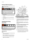
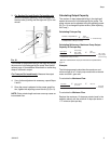
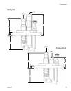
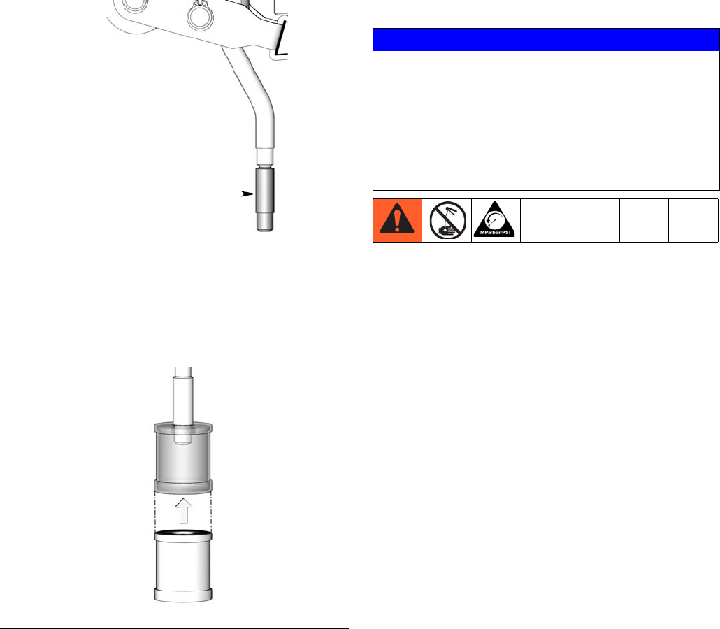
b. For all installations (whether the tube needs to
be trimmed or can be used without trimming),
press strainer onto end of the suction tube until
it “bottoms” (F
IG. 3).
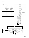
4. Orient pump so the roller bearing on the bottom of
the pump is aligned with the cam inside the reser-
voir.
5. Install pump on the reservoir by aligning the holes
(d) on either end of the pump with the mounting
holes (c) in the reservoir cover (F
IG. 1).
6. Install washers (f) and bolts (e) and wrench tighten
them securely. Torque bolts as recommended in
your reservoir instruction manual.
Setup
1. Expel all air from pump and relieve pressure (page
4).
NOTE:
• Do not connect the oil line to the pump outlet or
lube point until all air has been expelled.
• Use filtered oil when priming the pump.
• Filter oil with minimum 25 micron strainer.
Machine requirements may require a higher
cleanliness level.
• Maximum allowable inlet pressure:
- Pressure Fed Pump: 100 psi (0.69 MPa, 6.9
bar)
- Gravity Fed Pump With Sight Glass: 10 psi
(0.07 MPa, 0.7 bar)
• Minimum required inlet pressure for priming:
- Pressure Fed Pump: 1 psi (0.007 MPa, 0.07
bar)
- Gravity Fed Pump: N/A
- Suction Fed Pump: N/A
- Alarm Pump: N/A
2. Prime the pump using the procedure described in
the following section that relates to your pump
model.
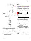
FIG. 2
FIG. 3
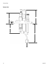
a
NOTICE
Any pressure applied to the pump inlet has the potential
to cause unrestricted flow from the pump outlet even in
a pump that is at rest or adjusted for zero stroke. To pre-
vent this from happening, install a check valve of a com-
parable pressure rating at the pump outlet.
NOTE: The internal “discharge check valve” does not
have a spring and is rated at zero psi.
I