


8 308608K
Operation
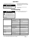
Pressure Relief Procedure
SKIN INJECTION HAZARD
To reduce the risk of serious bodily
injury, including fluid injection or splash-
ing in the eyes or on the skin, always
follow this procedure whenever you shut off the
pump, when checking or servicing any part of the
system, when installing or changing dispensing
devices, and whenever you stop dispensing.
WARNING
1. Close the bleed-type master air valve (required in
your system).
2. Hold a metal part of the dispensing valve firmly to
a grounded metal waste container and trigger the
valve to relieve the fluid pressure, or open the
drain valve (H).
If you suspect that the dispensing valve or hose is
completely clogged, or that pressure has not been fully
relieved after following the steps above, very slowly
loosen the hose end coupling and relieve pressure
gradually, then loosen completely, then clear the valve
or hose.
Startup and Adjustment
COMPONENT RUPTURE HAZARD
The maximum working pressure of each
component in the system may not be the
same. To reduce the risk of overpres-
surizing any component in the system, be sure you
know the maximum working pressure of each
component, including the air motor and pump.
Never exceed the maximum working pressure of
the lowest rated component in the system. Over-
pressurizing any component can result in rupture,
fire, explosion, property damage, and serious
injury.
To determine the fluid output pressure using the air
regulator reading, multiply the ratio of the pump by
the air pressure shown on the regulator gauge. For
example:
6 (:1) ratio x 180 psi air =
1080 psi fluid output
6 (:1) ratio x 7 bar air = 42 bar fluid output
6 (:1) ratio x 0.7 MPa air = 4.2 MPa fluid output
Limit the air to the pump so that no air line or fluid
line component or accessory is overpressurized.
WARNING
WARNING
HAZARDOUS VAPORS
The air motor exhaust coming out of the
muffler could contain harmful materials,
such as oil, antifreeze, or some of the
material being pumped.
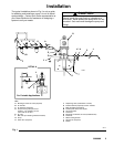
1. With the air regulator (C) closed, open the bleed-
type master air valves (A) or, if so equipped, join
the quick disconnect coupler (M) to the male fitting
(L).
2. Open the dispensing valve (J) into a grounded
metal waste container, making firm metal-to-metal
contact between the container and valve.
3. Open the pump air regulator (C) slowly, just until
the pump is running. When the pump is primed
and all air has been pushed out of the lines, close
the dispensing valve.
NOTE: When the pump is primed, and with sufficient
air supplied, the pump starts when the dis-
pensing valve is opened and shuts off when it
is closed.
4. If your system is equipped with a runaway valve (D
in Fig. 1), set it for your system configuration. See
manual 308201 for instructions on setting the
pump runaway valve.
5. Adjust the air regulator until you get sufficient flow
from the dispensing valve. Always run the pump
at the lowest speed necessary to get the desired
results. Do not exceed the maximum working
pressure of any component in the system.
6. If your pump accelerates quickly or is running too
fast, stop it immediately and check the fluid supply.
If the supply container is empty and air has been
pumped into the lines, prime the pump and lines
with fluid, or flush it and leave it filled with a com-
patible solvent. Be sure to eliminate all air from
the fluid lines. If your system has a runaway
valve, reset it according to the instructions in
manual 308201.
Never allow the pump to run dry of the fluid being
pumped. A dry pump will quickly accelerate to a
high speed, possibly damaging itself, and it may
get very hot.
CAUTION