


308608K 5
Installation
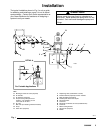
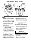
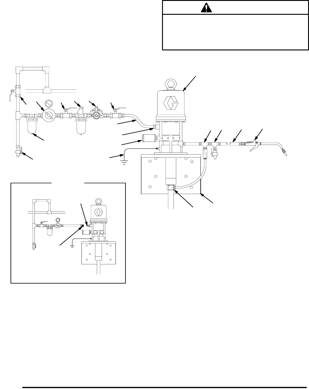
The typical installation shown in Fig.1 is only a guide
for selecting and installing a pump; it is not an actual
system design. Contact your Graco representative or
your Graco distributor for assistance in designing a
system to suit your needs.
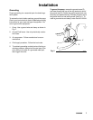
Always mount the pump firmly to a bracket or a
tank cover. Never operate the pump while it is not
mounted. Such use could damage the pump and
fittings.
CAUTION
D
N
A
C
A
KEY
A Bleed-type master air valve (required)
B Air line filter
C Air regulator and gauge
D Pump runaway valve (shown for
position) – not needed if you use
a low level cut-off valve
E Air inlet
F Ball valve (for releasing collected moisture)
G Pump
H Drain valve (required)
J Dispensing valve (model 222411 shown)
K Thermal relief kit (required), Part No. 240429
L Male quick-disconnect fitting
M Female quick-disconnect coupler
N Air line lubricator
P Fluid hose
R Electrically conductive air hose (218093 shown)
S Fluid inlet
T Wall-mounting bracket
Y Ground wire (required)
Z Muffler
Fig. 1
B
E
G
Y
H
P
J
L
M
DETAIL A
For Portable Applications
R
S
T
K
05610
A
F
Z
TI0890