


6 308608K
Installation
System Accessories
CAUTION
Do not hang the air accessories directly on the air
inlet (E). The fittings are not strong enough to
support the accessories and may cause one or
more to break. Provide a bracket on which to
mount the accessories.
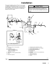
NOTE: Install the accessories in the order shown in
Fig. 1.
Four accessories are required in your system: an
air shut-off valve/air bleed device, fluid drain valve,
thermal relief kit, and ground wire. These accesso-
ries help reduce the risk of serious bodily injury
including fluid injection, splashing in the eyes or on
the skin, injury from moving parts if you are adjust-
ing or repairing the pump, and explosion from
static sparking.
The air bleed device relieves air trapped between it
and the air motor after the air supply is shut off.
Trapped air can cause the air motor to cycle unex-
pectedly, causing serious bodily injury if you are
adjusting or repairing the pump. Use either a
bleed-type master air valve (A) or a quick-discon-
nect coupler (M) and fitting (L). Install near the
pump air inlet, within easy reach of the pump.
The fluid drain valve (H) assists in relieving fluid
pressure in the displacement pump, hoses and
dispensing valve. Triggering the valve to relieve
pressure may not be sufficient.
The thermal relief kit assists in relieving pressure in
the pump, hose, and dispensing valve due to heat
expansion.
The ground wire reduces the risk of static sparking.
WARNING
1. Screw the muffler (5) into the 3/4-in. npt muffler
port, and tighten it using a wrench on the flats of
the muffler near the male threads.
2. Install an air line lubricator (N) for automatic air
motor lubrication.
3. Install the air regulator (C) to control pump speed
and pressure.
4. Install an air line filter (B) to remove harmful dirt
and contaminants from your compressed air
supply.
5. Install a bleed-type master air valve (A) to isolate
the accessories for servicing. See Fig. 1. To
order a bleed-type master air valve, order Part No.
107142.
As an alternative to a bleed-type master air valve,
you can install an air line quick disconnect coupler
(M) and fitting (L) to serve as an air-bleed device.
See Detail A in Fig. 1.
6. Install a drain valve (H) near the pump fluid outlet
to relieve fluid pressure in the hoses and gun when
opened. To order a fluid drain valve, order Part
No. 210658.
7. Install a thermal relief kit (K) on the dispensing
valve side of the pump. To order a 1600 psi
(110 bar, 11 MPa) thermal relief kit, order Part No.
240429.
8. Install a suitable fluid hose (P) and dispensing
valve (J).
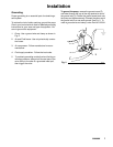
Cover Mount
For cover mounting, see the Mounting Hole Layout
on page 18.
Wall Mount
The pump shown in Fig. 1 is wall mounted. To order
the wall-mounting bracket, order Part No. 238245.