


8 309303
Installation
Air Line
WARNING
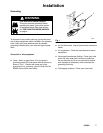
A bleed-type master air valve (B) is required in your
system to relieve air trapped between this valve
and the pump. See Fig. 2. Trapped air can cause
the pump to cycle unexpectedly, which could result
in serious injury, including splashing in the eyes or
on the skin, injury from moving parts, or contamina-
tion from hazardous fluids.
1. Install the air line accessories as shown in Fig. 2.
Mount these accessories on the wall or on a
bracket. Be sure the air line supplying the acces-
sories is electrically conductive.
a. The fluid pressure can be controlled in two
ways, either by controlling the air into the
pump with the air regulator (F) or the fluid out
of the pump with the fluid regulator (H).
b. Locate a bleed-type master air valve (B) close
to the pump, to relieve trapped air. See the
WARNING at left. Locate another air valve (E)
upstream from all air line accessories, to
isolate them during cleaning and repair.
c. Install an air line filter (D) to remove harmful
contaminants such as dirt, moisture, and oil
from the compressed air supply.
2. The air valve does not require lubrication.
3. Install an electrically conductive, flexible air hose
(C) between the accessories and the pump air inlet
(T). Use a minimum 1/4” (6.3 mm) ID air hose.
Screw an air line quick disconnect coupler (V) onto
the end of the air hose and screw the mating fitting
into the pump air inlet snugly. Do not connect the
coupler to the fitting yet.