


8 307983
Service
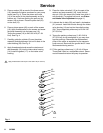
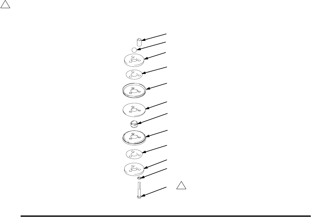
5. Place a washer (20) on each of the three screws
(19). Assemble the piston as shown for your pump
model (see Fig. 4). Place the piston valve seat
(13) in the center of the piston assembly so its lip
bottoms out. Continue stacking the parts on the
screws (19) as shown. Place the piston ball (22)
on the seat (13).
6. Place a piston spacer (42) on each of the screws
(19). Apply thread sealant to the screws and screw
the piston assembly into the lower cap (10).
Torque the screws (19) to 240–300 in-lb (27–34
N.m). See Fig. 4.
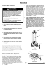
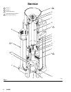
7. Carefully guide the cylinder (9) over the piston
assembly and displacement rod until it seats in the
outlet housing (24). See Fig. 2.
8. Apply thread sealant and screw the retainer and
seat assembly (16) into the intake valve housing
(14). Install the gasket (17*) on the intake valve
housing.
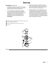
9. Place the intake valve ball (15) on the seat of the
retainer and seat assembly (16). Install the ball
stop pin (18) in the same set of holes from which it
was removed. (To readjust ball travel, see Piston
and Intake Valve Adjustment on page 4.)
10. Lubricate the tie bolts (30) and install a lockwasher
(31) on each. Install the tie bolts through the intake
valve housing (14) and up into the outlet housing
(24). Torque oppositely and evenly to 20–24 ft-lb
(27–33 N.m).
11. Torque the packing nut/wet-cup (1) 20–24 ft-lb
(27–33 N.m); do not overtighten or you may dam-
age the packings. Reconnect the displacement
pump to the motor as explained in your separate
pump manual. Reconnect the ground wire if it was
disconnected during service.
12. Fill the packing nut/wet-cup (1) 1/2 full of Graco
Throat Seal Liquid or a compatible solvent. Recon-
nect all hoses and return the pump to operation.
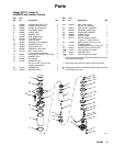
Fig. 4
1
Apply thread sealant and torque to 240–300 in–lb (27–34 N.m).
06076
11*
13
19
20
21n
22n
39*
42
11*
12n
21n
39*
1