


307983 5
Service
Before you start:
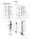
1. Have all necessary repair parts on hand. Recom-
mended spare parts are marked in the parts list
with a check mark, for example (3n).
2. Packing Repair Kits are available for some pumps.
See the parts list for your pump to order the cor-
rect kit. Use all the new parts in the kit for the best
results. Kit parts are indicated in the parts list with
an asterisk, for example (5*).
3. Always replace the glands when replacing the
packings, whether or not you use a repair kit.
4. Use a compatible solvent to clean parts. Inspect
for wear or damage and replace parts as needed.
5. Use light, waterproof grease wherever lubrication
is recommended.
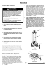
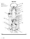
Disassembly (See Fig. 2)
WARNING
To reduce the risk of serious injury whenever you
are instructed to relieve pressure, always follow the
Pressure Relief Procedure on page 4.
1. Flush the pump, if possible. Relieve the pressure.
2. Disconnect the air and fluid lines. Remove the
pump from its mounting and clamp it in a vise.
Disconnect the displacement pump from the motor
as explained in your separate pump manual.
3. Loosen the packing nut/wet-cup (1). Unscrew and
remove the four tie bolts (30) and lockwashers
(31). Pull the intake valve housing (14) off the
pump.
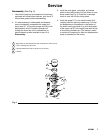
4. Remove and inspect the intake valve gasket (17).
Unscrew the retainer and seat assembly (16) from
the intake valve housing (14). Remove the ball
stop pin (18), noting which holes it is in. Remove
the intake valve ball (15). Handle the ball carefully
as it can be easily damaged.
5. Clean all parts of the intake valve and inspect
carefully for wear or damage. Inspect the seat (C)
of the retainer and seat assembly (16), but do not
attempt to remove it. If the seat is worn or dam-
aged, replace the entire retainer and seat assem-
bly.
6. Pull the pump cylinder (9) straight off the outlet
housing (24), being careful not to tilt it until it is
clear of the displacement rod (8) and piston as-
sembly (B).
7. Inspect the polished inner surface of the cylinder
(9) for scoring, wear or damage by running a finger
over the surface or holding the part up to a light at
an angle. Replace if necessary.
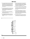
8. Remove the three screws (19) and washers (20),
and disassemble the piston. Be very careful when
handling the ball (22) and seat (13) as they can be
very easily damaged. Clean all parts and inspect
carefully for wear or damage. See Fig. 4.
9. Unscrew the packing nut/wet-cup (1) from the
outlet housing (24). Pull the displacement rod (8)
down out of the outlet housing. Remove and
inspect the outlet housing gasket (7).
10. Push the throat packings and glands (A) out of the
outlet housing (24). Clean the outlet housing and
throat packings, and inspect for wear or damage.
11. Inspect the polished outer surface of the displace-
ment rod (8) for scoring, wear or damage by
running a finger over the surface or holding the
part up to a light at an angle. Replace if necessary.
12. Do not disassemble the displacement rod
assembly unless necessary. Before disassem-
bling, carefully measure how far the adjustable
plunger rod (23) protrudes from the lower cap (10).
This determines the amount of piston ball (22)
travel. Screw the plunger rod (23) out of the dis-
placement rod assembly, and inspect the o-rings
(3) in place. Disassemble the upper and lower
caps (27, 10) from the displacement rod (8).
Inspect the o-rings (4) in place.