


4 307983
Service
Pressure Relief Procedure
WARNING
PRESSURIZED EQUIPMENT HAZARD
The system pressure must be manually relieved to
prevent the system from starting or spraying acci-
dentally. To reduce the risk of an injury from acci-
dental spray from the gun, splashing fluid, or
moving parts, follow the Pressure Relief Proce-
dure whenever you:
D are instructed to relieve the pressure,
D stop spraying,
D check or service any of the system equipment,
D or install or clean the spray nozzle.
1. Shut off the air or hydraulic power supply to the
pump.
2. Close the bleed-type master air valve (required in
air-powered systems).
3. Hold a metal part of the gun firmly to the side of a
grounded metal pail, and trigger the gun to relieve
pressure.
4. Open the drain valve (required in your system),
having a container ready to catch the drainage.
5. Leave the drain valve open until you are ready to
spray again.
If you suspect that the spray nozzle or hose is com-
pletely clogged, or that pressure has not been fully
relieved after following the steps above, very slowly
loosen the nozzle retaining ring or hose end coupling
and relieve pressure gradually, then loosen completely.
Now clear the nozzle or hose.
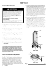
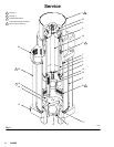
Piston and Intake Valve Adjustment
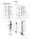
See Fig. 1. The fluid piston and intake check valves
are factory-set for pumping medium viscosity fluids.
The ball stop pin (18) in the intake valve is in the
lowest set of holes. The piston ball travel is set at
0.204 in. (5.2 mm), measured from the end of the
adjustable plunger rod (23) to the top of the ball (22).
This distance represents four complete turns of the rod
(23) from the top of the ball.
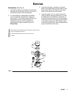
1. If you are pumping heavy viscosity fluid and
erratic pump operation develops, disassemble
the pump as explained on page 5. To increase
the ball travel in the intake valve, move the pin (18)
to the center or upper set of holes. To increase the
ball travel in the piston valve, place the piston in a
vise, loosen the upper cap (27) to relieve tension
on the plunger rod (23), and turn the plunger rod
counterclockwise two complete turns beyond its
factory-set position, or enough to set the total ball
travel to 0.306 in. (7.8 mm).
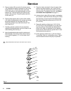
2. If you are pumping lighter viscosity fluid and
surging develops, disassemble the pump as
explained on page 5. To decrease the ball travel
in the intake valve, place the pin (18) in the lowest
set of holes. To decrease the ball travel in the
piston valve, place the piston in a vise, loosen the
upper cap (27) to relieve tension on the plunger
rod (23), and turn the plunger rod clockwise two
complete turns beyond its factory-set position, or
enough to set the total ball travel to 0.102 in. (2.6
mm).
06081
27
23
18
15
Piston Valve
Ball Travel
Intake Valve
16
22
Fig. 1
Ball Travel