


8 306563
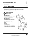
Service
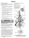
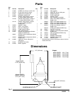
Regulator Disassembly
Shut off pump, close shutoff valve and relieve pressure
in regulator by triggering the spray gun. Remove the
regulator from the system.
1. Using the hex end of key (25), adjust screw (20) all
the way counterclockwise to relieve regulator
spring tension.
2. Remove outlet bushing (15) and counter-balance
spring (29) (Model 204500 only) from the body.
3. Unscrew valve stem (27) from diaphragm hanger
(28) with adjusting key. See Fig. 3.
4. Remove screws (1), regulator cap (17), spring
adjusting screw (20), spring (13), and spring
cap (30) (Model 204500 only).
5. Lift diaphragm (31) and hanger from body. Disas-
semble the hanger and diaphragm only if dam-
aged.
6. Unscrew valve seat (26) from body with a 9/16”
socket wrench. See Fig. 3.
7. Thoroughly inspect all parts and inspect for wear
or damage, replacing as necessary.
CAUTION
Use special care in handling the valve stem and seat
to avoid damaging the hard carbide parts.
Regulator Reassembly
Reassemble regulator in reverse order of Disassem-
bly. When inserting the diaphragm and hanger, be
sure that all surfaces are clean and smooth. Any dirt or
roughness could damage the diaphragm.
Note: Hold hanger (28) and valve stem (27) in place
with a finger so that the valve stem is correctly lined up
with the valve seat (26).
The hanger should be in line with one set of holes and
the nut should be torqued to 20 ft-lb (27 NSm). Turn the
valve stem snugly against the seat and then back off
1/2 turn on model 204500 and 3/4 turn on other mod-
els to set valve clearance. When installing the
cap (17), line up finger of spring adjusting nut (12) with
the groove in the cap (17) . Torque the six screws (1)
evenly to 120–130 in-lb (13.6–14.7 NSm) three times
consecutively, in the order shown in the TOP VIEW, to
compensate for diaphragm relaxation. See Fig. 3.
Note: If further service is needed, see notes on lu-
brication, thread sealant, and torque values in Fig. 4.
03372
03370
03371
Fig. 3
1
3
4
2
1
23
4
5
6
Gauge
25
17
1
1
27
29
15
28
26
31
2
30
13 3
32
12
20
3
28
10
5
5
See TOP VIEW for tightening sequence.
Lubricate with oil.
Lubricate with grease.
4
Torque to 20 ft-lb (27 NSm).
Hanger must be parallel
to diaphragm holes.
TOP VIEW
6
6
Torque to 120–130 in-lb
(13.6–14.7 NSm).