


5306563
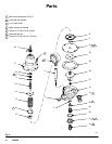
Installation
F
E
A
C
G
D
H
B
A
B
C
D
E
F
G
H
Regulator
Dispensing Unit
Gauge
Regulator Inlet
Regulator Outlet
Air Regulator
Supply Line
Accessory Outlet
KEY
Fig. 1
03363
TYPICAL INSTALLATION
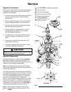
CAUTION
Before installing the regulator, check the tightness of
the screws (1). Refer to Fig. 3 for the tightening
sequence and the torque value. If the regulator leaks
during operation, check and torque the screws again.
In order to prevent damaging the regulator, blow out
and flush the supply line to remove any particles.
D Install regulator (A) in fluid supply line as close as
possible to spray gun or dispensing valve (B) for
easy operator control.
D Mount the regulator in an upright position so that
the gauge (C) can be easily read.
D If turning the gauge, reapply sealer to the threads,
and use a wrench on the inlet stud to turn gauge.
Regulator inlet (D) is 3/8 npsm (f) swivel and outlet
(E) is 3/8 npsm (m) rigid.
D Connect a fluid hose to regulator outlet (E) and
spray gun. Connect an air atomizing hose to the
spray gun and air regulator (F) See Fig. 1.
D To mount the regulator in a circulating system
supply line (G), install an accessory outlet (H). One
outlet (H) and air regulator (F) are required for each
spray gun. The accessory outlet (Part No. 204819)
may be ordered separately.