


307427 7
Installation
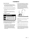
System Accessories
Refer to Fig. 2 and the Accessories section.
NOTE: To ensure maximum pump performance, be
sure that all accessories used are properly sized to
meet your system’s requirements.
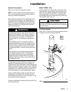
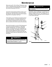
Most models are supplied with a needle-type air con-
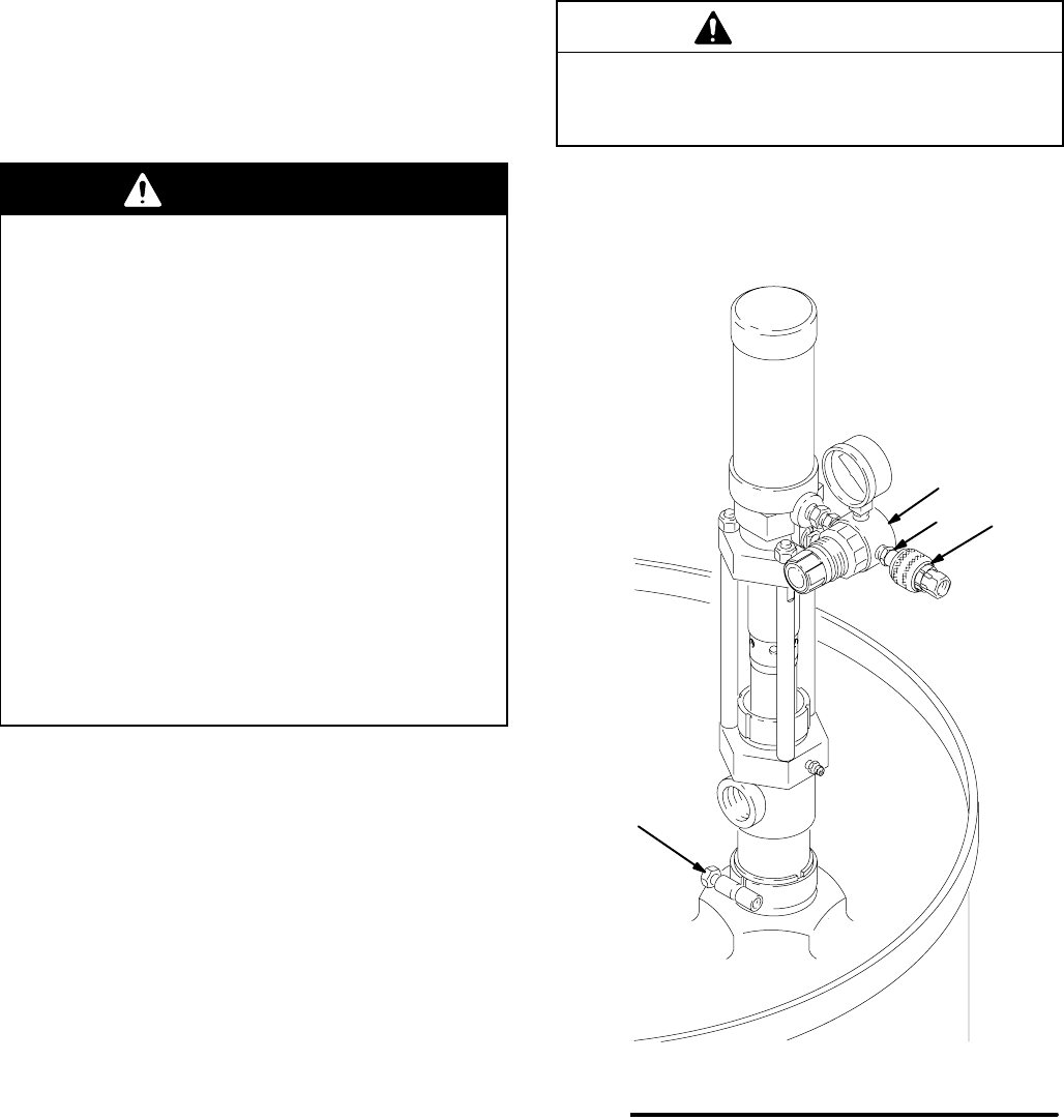
trol valve (K) at the pump air inlet. Model 226951 is
equipped with an air regulator kit (CC) instead (see
Fig. 3). All models are supplied with an air line quick
disconnect coupler (L) to connect the air line to the
pump and accessories.
WARNING
A bleed-type master air valve (D) and a fluid drain
valve (G) are required in your system, to help re-
duce the risk of serious injury, including splashing
fluid in the eyes or on the skin, and injury from
moving parts if you are adjusting or repairing the
pump.
The bleed-type master air valve (D) relieves air
trapped between this valve and the pump after the
pump is shut off. Trapped air can cause the pump
to cycle unexpectedly and result in serious injury,
including amputation. Locate the valve close to the
pump.
The fluid drain valve (G) helps relieve pressure in
the displacement pump, hose, and dispensing
valve when shutting off the pump. Actuating the
dispensing valve to relieve pressure may not be
sufficient, especially if there is a clog in the hose or
the dispensing valve.
For automatic air motor lubrication, install an air line
lubricator (C) downstream from the air regulator (if
supplied) and all other accessories. Install a bleed-type
master air valve (D) close to the pump. Next, install the
air regulator (CC), if supplied. Install an air line filter (E)
upstream from all other accessories, to remove harm-
ful dirt and moisture from the compressed air supply.
Using a suitable adapter, install the male disconnect
pin fitting (J) in the air filter inlet. Install the air line
quick disconnect coupler (L) on the air hose (F), but do
not connect it to the pin fitting yet.
Connect an electrically conductive fluid hose (M) to the
3/4 npt(f) fluid outlet.
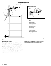
Model 226951 Only
Using moderate force, extend the pump suction tube,
insert the pump into the drum or tank bung hole, and
screw the bung adapter (B) tightly into the bung hole.
Lift the pump about 13 mm (0.5 in.) and tighten the
bung adapter (B) screw to hold the pump. Loosen the
vent plug (A). Refer to Fig. 2.
CAUTION
To prevent damaging the o-ring seals inside the suc-
tion tube, do not use excessive force when extending
the suction tube.
All Other Models
Refer to Fig. 2 and to the mounting accessories shown
on page 35 for pump mounting methods.
03763
Fig. 3
CC
JL
B
Model
226951
Shown