


307427 17
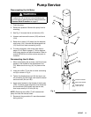
Displacement Pump Service
CARBON STEEL DISPLACEMENT PUMPS,
with leather, polyethylene, or
PTFE packings
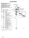
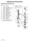
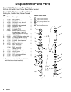
This procedure covers the following displacement
pumps. Refer to the parts drawings on the indicated
pages for an illustration of your pump.
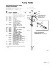
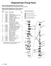
D Model 215953, page 18.
D Model 215956, page 18.
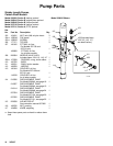
D Model 215954, page 19.
D Model 215957, page 19.
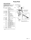
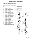
D Model 237254, page 20.
D Model 237449, page 21.
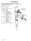
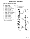
D Model 237255, page 22.
Before You Start
1. Disconnect the displacement pump from the air
motor as explained on page 11.
2. Be sure you have all the necessary repair parts on
hand to reduce downtime.
3. Repair Kits are available. For best results, use all
the new parts in the kit even if the old parts look
good. Refer to the parts drawing for your pump.
Intake Valve
1. Unscrew the intake valve housing (23) from the
cylinder (13), using a strap wrench. Disassemble
the valve and clean and inspect all parts.
NOTE: On Models 237254 and 237255, inspect the
ball (28) and seat in the housing (23) for wear or nicks.
2. Replace parts as necessary. Reassemble as
shown in the applicable parts drawing.
Piston Valve
1. Using a strap wrench, grip the cylinder (13) near
the outlet housing (6) and unscrew it from the
housing. Pull the cylinder down off the piston.
Check the inner surface of the cylinder for scoring
or wear by running a finger over the surface or
holding the part up to the light at an angle.
2. Loosen the lower nut (16) and unscrew the valve
housing (18) from the connecting rod (17). Un-
screw the piston stud (22).
3. Clean and inspect all piston parts. Replace parts
as necessary. Reassemble the piston parts as
shown, being sure that the lips of the u-cup pack-
ing (21) are facing up. Screw the piston stud (22)
into the valve housing (18) and torque to 31 NSm
(23 ft–lb).
4. When reassembling the piston to the connecting
rod (17), screw the connecting rod all the way into
the displacement rod (15). Tighten the upper nut
(16) against the displacement rod and torque to 33
NSm (24 ft–lb). Adjust the lower nut (16) to allow
3.1 mm (0.125 in.) free travel for the disk (19).
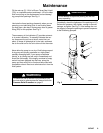
Throat Packings
1. Remove the cylinder (13) and piston as explained
previously. Remove the packing nut (1) and pull
the displacement rod (15) out of the top of the out-
let housing (6). Inspect the outer surface of the
displacement rod for scoring or wear by running a
finger over the surface or holding it up to the light
at an angle.
2. Remove the throat packings from the outlet hous-
ing (6).
3. Clean and inspect the parts for wear or damage.
Lubricate the packings before reassembly. Install
the parts one at a time, in the same position as
before. The lips of the v-packings must face down
against fluid pressure.
NOTE: On displacement pumps 215953, 215956, and
237254, install the two leather v-packings (4) below the
single PTFE v-packing (3).
4. Leave the packing nut (1) loose until the displace-
ment rod (15) has been installed.
CAUTION
Insert the displacement rod from the top of the outlet
housing to prevent shearing of the packings.
5. Tighten the packing nut just enough to prevent
leaking. Overtightening can damage the packings.
6. Reconnect the displacement pump to the air motor
as explained on page 11.