


15
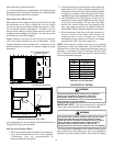
SET EVAPORATOR FAN RPM
Actual RPM’s must be set and verified with a tachometer or
strobe light. Refer to Appendices A and B for basic unit fan
RPM. Refer also to “Airflow” section of this manual. With
disconnect switch open, disconnect thermostat wires from
terminals Y and W. This will prevent heating and mechanical
cooling from coming on. Place a jumper wire across termi-
nals R and G at TB1 terminal block. Close disconnect switch;
evaporator fan motor will operate so RPM can be checked.
For gas heat units, the airflow must be adjusted so that the
air temperature rise falls within the ranges given stated on
Data Plate (see Appendix A - Blower Performance).
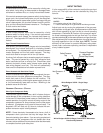
TENSION AND ALIGNMENT ADJUSTMENT
Correct belt tension is very important to the life of your belt.
Too loose a belt will shorten its life; too tight, premature mo-
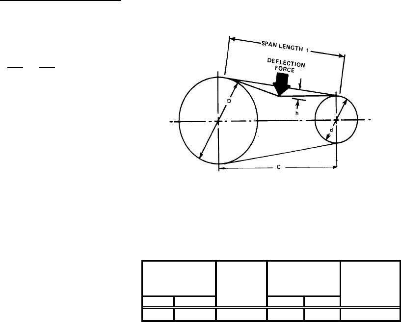
tor and bearing failure will occur. Check you belt drive for
adequate “run-in” belt tension by measuring the force required
to deflect the belt at the midpoint of the span length. Belt
tension force can be measured using a belt tension gauge,
available through most belt drive manufacturers.
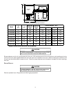
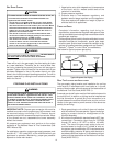
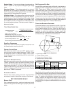
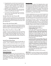
Belt Tension Adjustment
t = Span length, inches
C = Center distance, inches
D = Larger sheave diameter, inches
d = Smaller sheave diameter, inches
h = Deflection height, inches
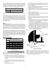
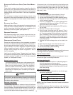
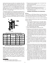
BELT DRIVE USED NEW
AX Standard 3.0 to 4.0 4.2 ± 0.5 5.5 ± 0.5 0.313
DEFLECTION
FORCE (lbs)
TYPE DEFLECTION
(in)
SMALL
SHEAVE
DIAMETER
(in)
Recommended Pounds of Force Per Belt
New V-belts will drop rapidly during the first few hours of use.
Check tension frequently during the first 24 hours of opera-
tion. Tension should fall between the minimum and maximum
force. To determine the deflection distance from a normal
position, measure the distance from sheave to sheave using
a straightedge or a cord. This is your reference line. On mul-
tiple belt drives, an adjacent undeflected belt can be used as
a reference.
System Voltage - That nominal voltage value assigned to a
circuit or system for the purpose of designating its voltage
class.
Nameplate Voltage - That voltage assigned to a piece of
equipment for the purpose of designating its voltage class
and for the purpose of defining the minimum and maximum
voltage at which the equipment will operate.
Utilization Voltage - The voltage of the line terminals of the
equipment at which the equipment must give fully satisfac-
tory performance. Once it is established that supply voltage
will be maintained within the utilization range under all sys-
tem conditions, check and calculate if an unbalanced condi-
tion exists between phases. Calculate percent voltage un-
balance as follows.
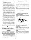
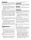
Three Phase Models Only
3) PERCENT VOLTAGE
UNBALANCE
2) MAXIMUM VOLTAGE DEVIATIONS
FROM AVERAGE VOLTAGE
1) AVERAGE VOLTAGE
HOW TO USE THE FORMULA:
EXAMPLE: With voltage of 220, 216, and 213
1) Average Voltage = 220+216+213=649 / 3 = 216
2) Maximum Voltage Deviations from Average Voltage = 220 - 216 = 4
3) Percent Voltage Unbalance = 100 x = = 1.8%
Percent voltage unbalance MUST NOT exceed 2%
.
4
216
400
216
= 100 X
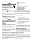
FIELD DUCT CONNECTIONS
Verify that all duct connections are tight and that there is no
air bypass between supply and return.
CONTROL VOLTAGE CHECK
With disconnect switch in the open “OFF” position, discon-
nect blue wire from low voltage transformer TRANS1. Close
the disconnect switch to energize TRANS1 control trans-
former. Check primary and secondary (24V) of control trans-
former TRANS1.
THERMOSTAT PRELIMINARY CHECK
With disconnect switch open and blue wire disconnected from
TRANS1 transformer, attach one lead of ohmmeter to termi-
nal R on TB1 terminal block. Touch, in order, the other ohm-
meter lead to terminals Y1, Y2 and G at TB1 terminal block.
There must be continuity from terminal R to terminals Y and
G. R to Y indicates cool. R to G indicates fan (auto). Replace
blue wire on TRANS1 transformer.
FILTER SECTION CHECK
Remove filter section access panels and check that filters
are properly installed. Note airflow arrows on filter frames.
BELT DRIVE MODELS ONLY
BEARING CHECK
Prior to energizing any fans, check and make sure that all
setscrews are tight so that bearings are properly secured to
shafts.