


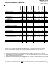
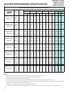

FURNACE SPECIFICATIONS
9
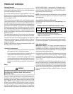
1. These furnaces are manufactured for natural gas operation. Optional Kits are available for conversion to propane gas operation.
2. For elevations above 2000 ft. the rating should be reduced by 4% for each 1000 ft. above sea level. The furnace must not be derated, orifice
changes should only be made if necessary for altitude.
3. The total heat loss from the structure as expressed in TOTAL BTU/HR must be calculated by the manufactures method in accordance with the
"A.S.H.R.A.E. GUIDE" or "MANUAL J-LOAD CALCULATIONS" published by the AIR CONDITIONING CONTRACTORS OF AMERICA. The total
heat loss calculated should be equal to or less than the heating capacity. Output based on D.O.E. test procedures, steady state efficiency times
output.
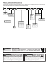
4. Minimum Circuit Ampacity calculated as: (1.25 x Circulator Blower Amps) + I.D. Blower Amps.
Unit specifications are subject to change without notice. ALWAYS refer to the unit's serial plate for the most up-to-date general and electrical information.
(1)
Wire size should be determined in accordance with National Electrical Codes. Extensive wire runs will require larger wire sizes.
(2)
Maximum Overcurrent Protection Device: May use Time Delay Fuse or HACR type Circuit Breaker of the same size as noted.
(3)
See Installation Instructions for appropriate vent diameter, length and number of elbows.
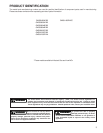
GMS8[040-100]BB
GMS81205D*BA
GMS81405DNCC
MODEL
GMS80403A*BB
GMS80603A*BB
GMS80604B*BB
GMS80804B*BB
GMS80805C*BB
GMS81005C*BB
GMS81205D*BA
GMS81405DNCC
Btuh Input (US) High Fire 40,000 60,000 60,000 80,000 80,000 100,000 120,000 140,000
Output (US) High Fire 32,000 48,000 48,000 64,000 64,000 80,000 96,000 112,000
A.F.U.E. 80% 80% 80% 80% 80% 80% 80% 80%
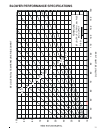
Rated External Static (" w.c.) .20 - .50 .20 - .50 .20 - .50 .20 - .50 .20 - .50 .20 - .50 .20 - .50 .20 - .50
Temperature Rise (°F) 25 - 55 25 -55 20 - 50 35 - 65 35 - 65 35 - 65 40 - 70 40 - 70
High Stage Pressure Switch
Trip Point (" w.c.)
-0.70 -0.75 -0.75 -0.70 -0.75 -0.70 -0.80 -0.80
Blower Wheel (D" x W") 10 X 6 10 x 6 10 x 8 10X8 10x10 10X10 11x10 11x10
Blower Horsepower 1/3 1/3 1/2 1/2 1/2 1/2 3/4 3/4
Blower Speeds 44444444
Max CFM @ 0.5 E.S.P. 1298 1157 1883 1725 1960 1974 2131 2131
Power Supply 115-60-1 115-60-1 115-60-1 115-60-1 115-60-1 115-60-1 115-60-1 115-60-1
Minimum Circuit Ampacity (MCA)
(1)
8.5 8.5 12.9 12.9 12.9 12.9 15.2 14.7
Maximum Overcurrent Device
(2)
15 15 15 15 15 15 15 15
Transformer (VA) 40 40 40 40 40 40 40 40
Heat Anticipator (Amps) 0.7 0.7 0.7 0.7 0.7 0.7 0.7 0.7
Primary Limit Setting (°F) 210° 150° 150° 150° 160° 150° 160° 160°
Auxiliary Limit Setting (°F) 120° 120° 120° 120° 120° 120° 120° 120°
Rollout Limit Setting (°F) 300° 300° 300° 300° 300° 300° 300° 300°
Gas Supply Pressure
(Natural/Propane) (" w.c.)
7 / 11 7 / 11 7 / 11 7 / 11 7 / 11 7 / 11 7 / 11 7 / 11
Manifold Pressure
(Natural/Propane) High Stage (" w.c.)
3.5 / 10 3.5 / 10 3.5 / 10 3.5 / 10 3.5 / 10 3.5 / 10 3.5 / 10 3.5 / 10
Orifice Size (Natural/Propane) #45 / #55 #45 / #55 #45 / #55 #45 / #55 #45 / #55 #45 / #55 #45 / #55 #43 / #55
Number of Burners 23344566
Vent Connector Diameter (inches)
(3)
44444444
Shipping Weight (lbs.) 84 88 98 106 114 118 130 130