


SERVICING
59
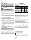
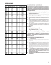
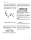
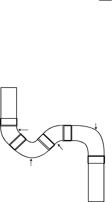
3. An oil trap is required at the evaporator only if the
condenser is above the evaporator. Preformed oil
traps are available at most HVAC supply houses, or oil
traps may be created by brazing tubing elbows together
(see diagram below). Remember to add the equivalent
length from oil traps to the equivalent length calculation
of the suction line. For example, if you construct an oil
trap using two 45° elbows, one short and one long 90°
elbow in a ¾” diameter suction line, the additional
equivalent length would be 0.7+ 0.7+1.7+1.5, which
equals 4.6 feet (refer to table 9).
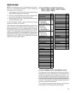
Long Radius Street Ell
45°
Street
Ell
45 °
Ell
Short Radius
Street Ell
Oil Trap Construction
Fig 7. Oil Trap
4. Low voltage wiring. Verify low voltage wiring size is
adequate for the length used since it will be increased in
a long line application.
System Charging
R22 condensers are factory charged for 15 feet of line set. To
calculate the amount of extra refrigerant (in ounces) needed
for a line set over 15 feet, multiply the additional length of line
set by 0.6 ounces. Note for the formula below, the linear feet
of line set is the actual length of liquid line (or suction line,
since both should be equal) used, not the equivalent length
calculated for the suction line.
Extra refrigerant needed =
(Linear feet of line set – 15 ft) x X oz/ft.
Where X = 0.6 for 3/8" liquid tubing
Remember, for condensers with a liquid valve connection
less than 3/8" diameter, 3/8" liquid tubing is required for a
line set longer than 25 feet.
Follow the charging procedures in the outdoor unit I/O manual
to ensure proper superheat and sub-cooling levels, especially
on a system with a TXV installed in the indoor unit. Heat
pumps should be checked in both heating and cooling mode
for proper charge level. This guideline is meant to provide
installation instructions based on most common long line set
applications. Installation variables may affect system opera-
tion.
NO ADDITIONAL COMPRESSOR OIL IS NEEDED FOR
LONG LINE SET APPLICATIONS
ON RESIDENTIAL SPLIT SYSTEMS.
S-122 REVERSING VALVE REPLACEMENT
Remove the refrigerant charge from the system.
When brazing a reversing valve into the system, it is of
extreme importance that the temperature of the valve does
not exceed 250° F. at any time.
Wrap the reversing valve with a large rag saturated with water.
"Re-wet" the rag and thoroughly cool the valve after each
brazing operation of the four joints involved. The wet rag
around the reversing valve will eliminate conducting of heat to
the valve body when brazing the line connection.
The use of a wet rag sometimes can be a nuisance. There are
commercial grades of heat absorbing paste that may be
substituted.
After the valve has been installed leak test, evacuate and
recharge.
S-202 DUCT STATIC PRESSURES AND/OR
STATIC PRESSURE DROP
ACROSS COILS
This minimum and maximum allowable duct static pressure
for the indoor sections are found in the specifications section.
Tables are also provided for each coil, listing quantity of air
(CFM) versus static pressure drop across the coil.
Too great an external static pressure will result in insufficient
air that can cause icing of the coil. Too much air can cause
poor humidity control and condensate to be pulled off the
evaporator coil causing condensate leakage. Too much air
can also cause motor overloading and in many cases this
constitutes a poorly designed system.