


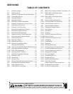
SERVICING
33
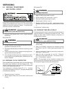
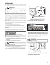
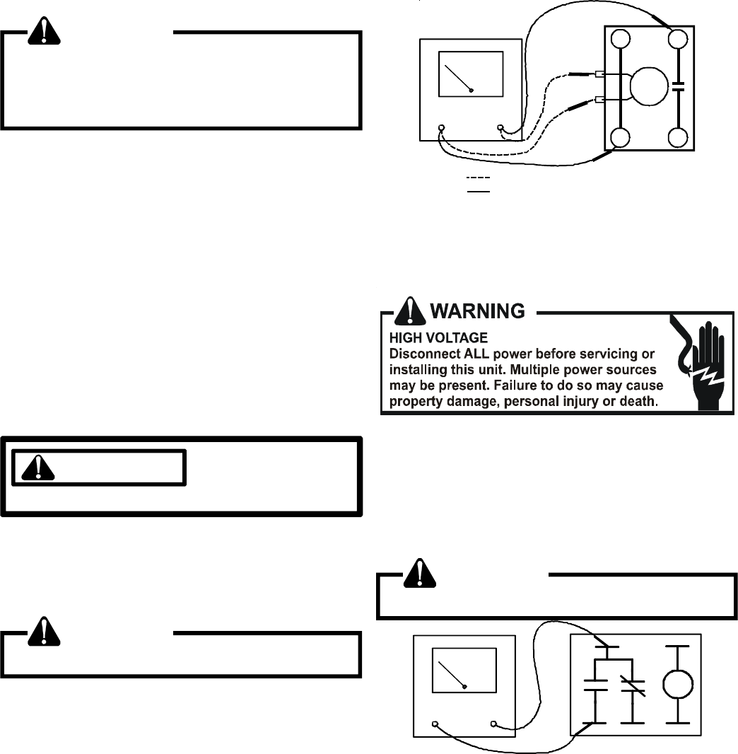
S-7 CHECKING CONTACTOR AND/OR RELAYS
WARNING
HIGH VOLTAGE!
Disconnect ALL power before servicing or installing.
Multiple power sources may be present. Failure to do
so may cause property damage, personal injury
or death.
The compressor contactor and other relay holding coils are
wired into the low or line voltage circuits. When the control
circuit is energized, the coil pulls in the normally open
contacts or opens the normally closed contacts. When the
coil is de-energized, springs return the contacts to their
normal position.
NOTE: Most single phase contactors break only one side of
the line (L1), leaving 115 volts to ground present at most
internal components.
1. Remove the leads from the holding coil.
2. Using an ohmmeter, test across the coil terminals.
If the coil does not test continuous, replace the relay or
contactor.
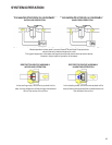
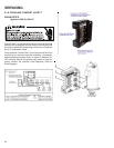
S-8 CHECKING CONTACTOR CONTACTS
DISCONNECT ELECTRICAL POWER SUPPLY.
WARNING
Disconnect Electrical Power Supply:
1. Disconnect the wire leads from the terminal (T) side of the
contactor.
2. With power ON, energize the contactor.
WARNING
Line Voltage now present.
3. Using a voltmeter, test across terminals.
A. L2 - T1 - No voltage indicates CC1 contacts open.
If a no voltage reading is obtained - replace the contactor.
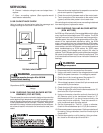
VOLT/OHM
METER
T1
T2
L1L2
CC
Ohmmeter for testing holding coil
Voltmeter for testing contacts
TESTING COMPRESSOR CONTACTOR
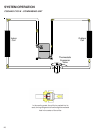
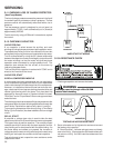
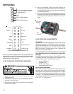
S-9 CHECKING FAN RELAY CONTACTS
1. Disconnect wires leads from terminals 2 and 4 of Fan
Relay Cooling and 2 and 4, 5 and 6 of Fan Relay Heating.
2. Using an ohmmeter, test between 2 and 4 - should read
open. Test between 5 and 6 - should read continuous.
3. With power ON, energize the relays.
WARNING
Line Voltage now present.
1
2
3
4
5
OHMMETER
TESTING FAN RELAY
4. Using an ohmmeter, test between 2 and 4 - should read
continuous . Test between 5 and 6 - should read open.
5. If not as above, replace the relay.