


SERVICING
45
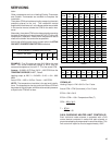
S-40 AR*F & MBR ELECTRONIC BLOWERS
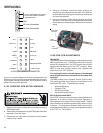
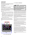
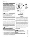
TIME DELAY RELAY
The MBR contains an Electronic Blower Time Delay Relay
board, B1370735. This board provides on/off time delays for
the blower motor in cooling and heat pump heating demands
when “G” is energized.
During a cooling or heat pump heating demand, 24Vac is
supplied to terminal “G” of the EBTDR to turn on the blower
motor. The EBTDR initiates a 7 second delay on and then
energizes it’s onboard relay. The relay on the EBTDR board
closes it’s normally open contacts and supplies power to the
blower motor. When the “G” input is removed, the EBTDR
initiates a 65 second delay off. When the 65 seconds delay
expires the onboard relay is de-energized and it’s contacts
open and remove power from the blower motor.
During an electric heat only demand, “W1” is energized but
“G” is not. The blower motor is connected to the normally
closed contacts of the relay on the EBTDR board. The other
side of this set of contacts is connected to the heat se-
quencer on the heater assembly that provides power to the
first heater element. When “W1” is energized, the sequencer
will close it’s contacts within 10 to 20 seconds to supply
power to the first heater element and to the blower motor
through the normally closed contacts on the relay on the
EBTDR. When the “W1” demand is removed, the sequencer
opens it contacts within 30 to 70 seconds and removes power
from the heater element and the blower motor.
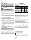
The EBTDR also contains a speedup terminal to reduce the
delays during troubleshooting of the unit. When this terminal
is shorted to the common terminal, “C”, on the EBTDR board,
the delay ON time is reduced to 3 seconds and the delay OFF
time is reduced to 5 second.
Two additional terminals, M1 and M2, are on the EBTDR
board. These terminals are used to connect the unused leads
from the blower motor and have no affect on the board’s
operation.
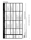
SEQUENCE OF OPERATION
This document covers the basic sequence of operation for a
typical application with a mercury bulb thermostat. When a
digital/electronic thermostat is used, the on/off staging of the
auxiliary heat will vary. Refer to the installation instruc-
tions and wiring diagrams provided with the MBR and
AR*F for specific wiring connections and system con-
figuration.
AR*F & MBR
WITH SINGLE STAGE CONDENSERS
1.0 Cooling Operation
1.1 On a demand for cooling, the room thermostat energizes
“G” and “Y” and 24Vac is supplied to “Y” at the condensing
unit and the “G” terminal on the EBTDR board.
1.2 The compressor and condenser fan are turned on and
after a 7 second on delay, the relay on the EBTDR board
is energized and the blower motor starts.
1.3 When the cooling demand “Y” is satisfied, the room
thermostat removes the 24Vac from “G” and “Y”.
1.4 The compressor and condenser fan are turned off and after
a 65 second delay off, the relay on the EBTDR board is de-
energized and the blower is turned off.
2.0 Heating Operation
2.1 On a demand for heat, the room thermostat energizes
“W1” and 24Vac is supplied to heat sequencer, HR1, on
the heater assembly.
2.2 The contacts M1 and M2 will close within 10 to 20
seconds and turn on heater element #1. The normally
closed contacts on the EBTDR are also connected to
terminal M1. When M1 and M2 close, the blower motor
will be energized thru the normally closed contacts on the
EBTDR board. At the same time, if the heater assembly
contains a second heater element, HR1 will contain a
second set of contacts, M3 and M4, which will close to
turn on heater element #2.
Note: If more than two heater elements are on the heater
assembly, it will contain a second heat sequencer, HR2,
which will control the 3
rd
and 4
th
heater elements if available.
If the first stage heat demand, “W1” cannot be satisfied by the
heat pump, the temperature indoors will continue to drop. The
room thermostat will then energize “W2” and 24Vac will be
supplied to HR2 on the heater assembly. When the “W2”
demand is satisfied, the room thermostat will remove the
24Vac from HR2. The contacts on HR2 will open between 30
to 70 seconds and heater elements #3 and #4 will be turned
off. On most digital/electronic thermostats, “W2” will
remain energized until the first stage demand “W1” is
satisfied and then the “W1” and “W2” demands will be
removed.
2.3 When the “W1” heat demand is satisfied, the room
thermostat will remove the 24Vac from HR1. Both set of
contacts on the relay opens within 30 to 70 seconds and
turn off the heater element(s) and the blower motor.
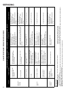
AR*F & MBR
WITH SINGLE STAGE HEAT PUMPS
3.0 Cooling Operation
On heat pump units, when the room thermostat set to the
cooling mode, 24Vac is supplied to “O” which energizes the
reversing valve. As long as the thermostat is set for cooling,
the reversing valve will be in the energized position for cooling.
3.1 On a demand for cooling, the room thermostat energizes
“G” and “Y” and 24Vac is supplied to “Y” at the heat pump
and the “G” terminal on the EBTDR board.
3.2 The heat pump turned on in the cooling mode and after a
7 second on delay, the relay on the EBTDR board is
energized and the blower motor starts.
3.3 When the cooling demand is satisfied, the room thermo-
stat removes the 24Vac from “G” and “Y”.
3.4 The heat pump is turned off and after a 65 second delay
off, the relay on the EBTDR board is de-energized and the
blower motor is turned off.