


50
PRESSURE S WITCHES
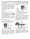
The pressure switches are normally-open (closed during opera-
tion) negative air pressure-activated switches. They monitor the
airflow (combustion air and flue products) through the heat ex-
changer via pressure taps located on the induced draft blower and
the coil front cover. These switches guard against insufficient air-
flow (combustion air and flue products) through the heat exchanger
and/or blocked condensate drain conditions.
FLAME S ENSOR
The flame sensor is a probe mounted to the burner/manifold as-
sembly which uses the principle of flame rectification to determine
the presence or absence of flame.
T
ROUBLESHOOTING
ELECTROSTATIC D ISCHARGE (ESD) PRECAUTIONS
NOTE: Discharge body’s static electricity before touching unit.
An electrostatic discharge can adversely affect electrical
components.
Use the following precautions during furnace installation and ser-
vicing to protect the integrated control module from damage. By
putting the furnace, the control, and the person at the same elec-
trostatic potential, these steps will help avoid exposing the inte-
grated control module to electrostatic discharge. This procedure
is applicable to both installed and uninstalled (ungrounded) fur-
naces.
1. Disconnect all power to the furnace. Do not touch the
integrated control module or any wire connected to the
control prior to discharging your body’s electrostatic charge
to ground.
2. Firmly touch a clean, unpainted, metal surface of the furnace
away from the control. Any tools held in a person’s hand
during grounding will be discharged.
3. Service integrated control module or connecting wiring
following the discharge process in step 2. Use caution not
to recharge your body with static electricity; (i.e., do not
move or shuffle your feet, do not touch ungrounded objects,
etc.). If you come in contact with an ungrounded object,
repeat step 2 before touching control or wires.
4. Discharge your body to ground before removing a new
control from its container. Follow steps 1 through 3 if
installing the control on a furnace. Return any old or new
controls to their containers before touching any ungrounded
object.
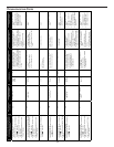
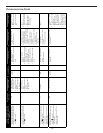
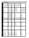
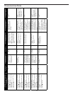
DIAGNOSTIC C HART
HIGHVOLTAGE!
T
O
AVOID
PERSONAL
INJURY
OR
DEATH
DUE
TO
ELECT RICAL
SHOCK
,
DISCONNECT
ELECT RICAL
POWER
BEF ORE
PERFORMING
ANY
SERVICE
OR
MAINTENANCE
.
WARNING
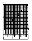
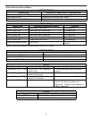
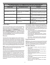
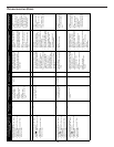
Refer to the Troubleshooting Codes for assistance in determining
the source of unit operational problems. The dual 7-segment LED
display will display an error code that may contain a letter and
number. The error code may be used to assist in troubleshooting
the unit.
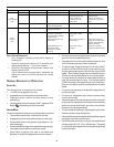
RESETTING F ROM L OCKOUT
Furnace lockout results when a furnace is unable to achieve igni-
tion after three attempts during a single call for heat. It is charac-
terized by a non-functioning furnace and a E
0 code displayed on
the dual 7-segment display. If the furnace is in “lockout”, it will (or
can be) reset in any of the following ways.
1. Automatic reset. The integrated control module will
automatically reset itself and attempt to resume normal
operations following a one hour lockout period.
2. Manual power interruption. Interrupt 115 volt power to the
furnace.
3. Manual thermostat cycle. Lower the thermostat so that
there is no longer a call for heat for 1 -20 seconds then
reset to previous setting.
NOTE: If the condition which originally caused the lockout still
exists, the control will return to lockout. Refer to the Troubleshooting
Codes for aid in determining the cause.
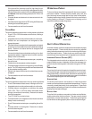
M
AINTENANCE
T
O
AVOID
ELECT RICAL
SHOCK
,
INJURY
OR
DEATH
,
DISCONNECT
ELECT RICAL
POWER
BEFORE
PERFORMING
ANY
MAINTENANCE
.I
F
YOU
MUST
HANDLE
THE
IGNITER
,
HANDLE
WITH
CARE
.T
OUCHING
THE
IGNITER
ELEMENT
WITH
BARE
FINGERS
,
ROUGH
HANDLING
OR
VIBRATION
COULD
DAMAGE
THE
IGNITER
RESULTING
IN
PREM ATURE
FAILURE
.O
NLY
A
QUALIFIED
SERVICER
SHOULD
EVER
HANDLE
THE
IGNITER
.
WARNING