


35
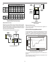
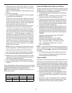
600 800 1000 1200 1400 1600 2000
0603__XA --- --- 564* 564* 672 768
0805__XA --- --- --- 752* 752* 768 960
1005__XA
1155__XA
--- --- --- 940* 940* 940* 960
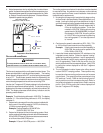
600 800 1000 1200 1400 1600 2000
0604__XA --- --- 641* 641* 672 768 ---
0805__XA
1005__XA
--- --- --- 854* 854* 854* 960
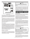
Input
Airflow
UPFLOW
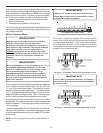
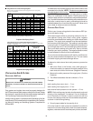
COOLING AIRFLOW REQUIREMENT (CFM)
COUNTERFLOW
COOLING AIRFLOW REQUIREMENT (CFM)
Input
Airflow
*Minimum filter area dictated by heating airflow requirement.
Disposable Minimum Filter area (sq. in)
[Based on 300 ft/min filter face velocity]
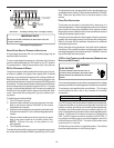
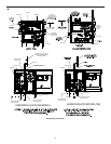
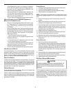
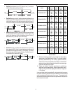
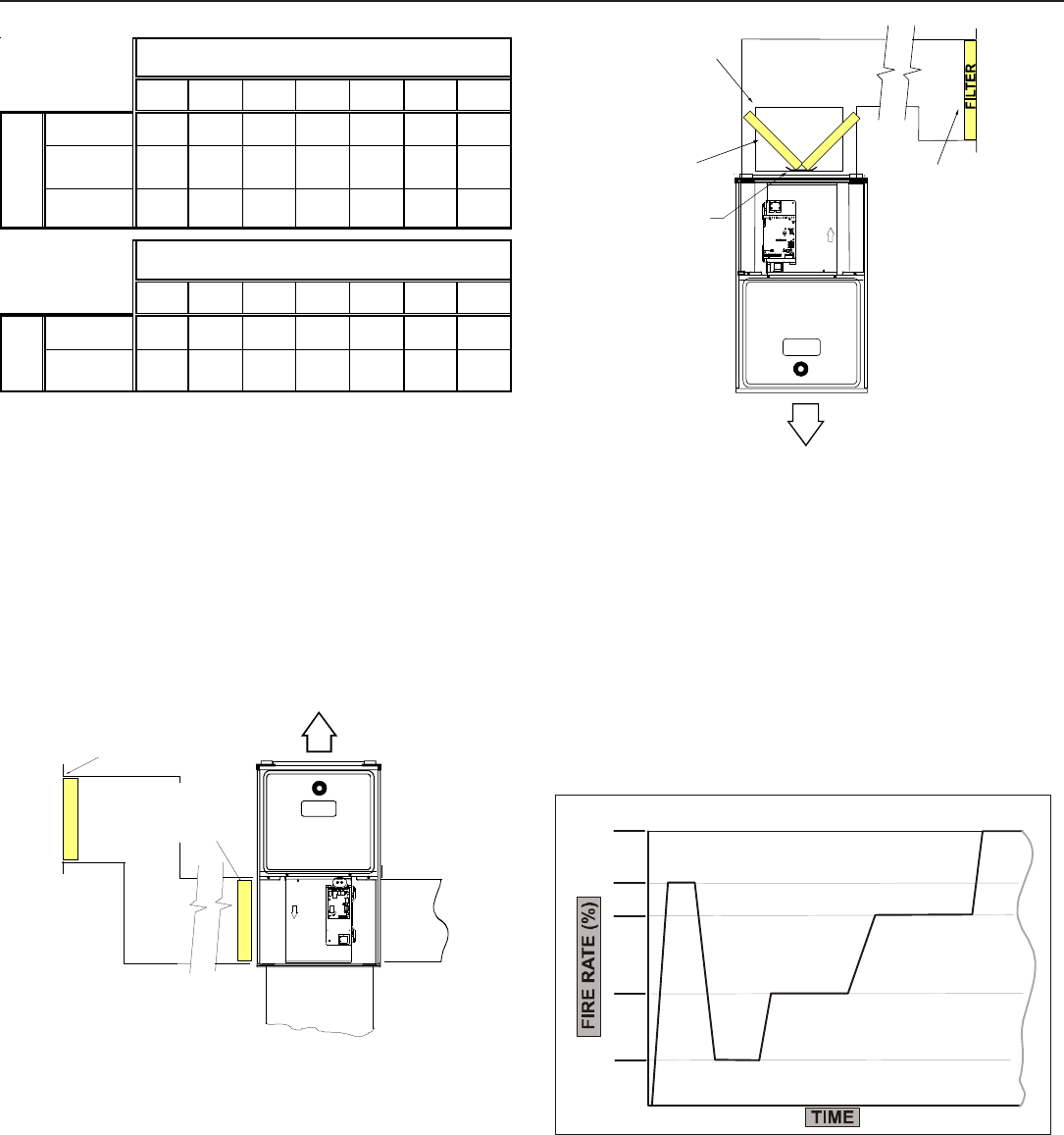
UPRIGHT I NSTALLATIONS
Depending on the installation and/or customer preference, differ-
ing filter arrangements can be applied. Filters can be installed in
the central return register or a side panel external filter rack kit
(upflows). As an alternative a media air filter or electronic air cleaner
can be used as the requested filter.
The following figure shows possible filter locations.
FILTER
AIR FLOW
CENTRAL
RETURN
GRILLE
FILTER
SIDE RETURN
EXTERNAL FILTER
RACK KIT
(EITHER SIDE)
Possible Upright Upflow
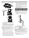
F
I
L
T
ER
AIR FLOW
CENTRAL
RETURN
GRILLE
RETURN
DUCT
F
I
L
T
E
R
FILTER
SUPPORT
BRACKET
(Field Supplied)
FILTER
ACCESS
DOOR
Possible Upright Counterflow
Filter Locations
HORIZONTAL I NSTALLATIONS
Filters must be installed in either the central return register or in
the return air duct work.
S
TARTUP
P
ROCEDURE
& A
DJUSTMENT
Furnace must have a 115 VAC power supply properly connected
and grounded. Proper polarity must be maintained for correct
operation. In addition to the following start-up and adjustment
items, refer to further information in Operational Checks section.
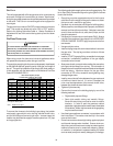
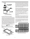
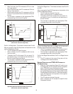
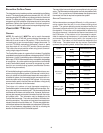
MIN.
57%
78%
(80%)
100%
IGNITION
UNIT CALL FOR HEAT ENDS
10 MINS.
8 MINS.
2 MINS.
Operation with Conventional 1-Stage Thermostat
(DIP switch selections 1-Stage heat)
Call for heat, thermostat energizes W1 on IFC (W2 input is
ignored).
After a successful Light Off Sequence and expiration of the
Ignition Stabilization Period: