


12
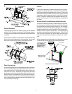
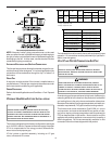
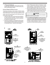
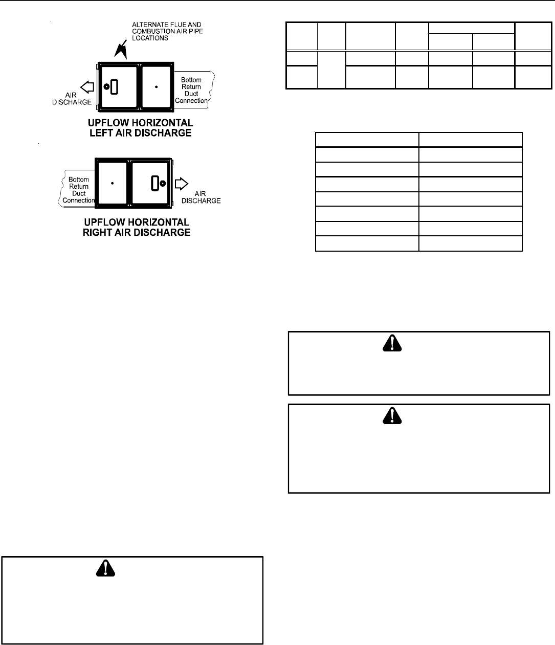
Recommended Installation Positions
NOTE: Alternate “vertical” piping connections can not be used
when an upflow furnace is installed with supply air discharging to
the right, or when a counterflow furnace is installed with supply air
discharging to the left. In either case, use the standard flue and
combustion air piping connections.
ALTERNATE E LECTRICAL AND G AS L INE CONNECTIONS
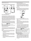
This furnace has provisions allowing for electrical and gas line con-
nections through either side panel. In horizontal applications the
connections can be made either through the “top” or “bottom” of
the furnace.
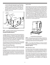
DRAIN P AN
A drain pan must be provided if the furnace is installed above a
conditioned area. The drain pan must cover the entire area under
the furnace (and air conditioning coil if applicable).
FREEZE PROTECTION
Refer to Horizontal Applications and Conditions - Drain Trap and
Lines.
P
ROPANE
G
AS
/H
IGH
A
LTITUDE
I
NSTALLATIONS
WARNING
P
OSSIBLE
PROPERTY
DAMAGE
,
PERSONAL
INJURY
OR
DEATH
MAY
OCCUR
IF
THE
CORRECT
CONVERSION
KITS
ARE
NOT
INSTALLED
.T
HE
APPRO PRIATE
KITS
MUST
BE
APPLIED
TO
ENSURE
SAFE
AND
PROPER
FURNACE
OPE RATION
.A
LL
CONVERSIONS
MUST
BE
PERFORMED
BY
A
QUALIFIED
INSTALLER
OR
SERVICE
AGENCY
.
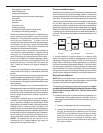
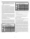
This furnace is shipped from the factory configured for natural gas
up to 10,000 ft. altitude. Propane conversions require the proper
LP kit to compensate for the energy content difference be-
tween natural and propane gas.
LP kits include a manifold assembly, including an LP gas
valve, orifices and LP burners.
High Stage Low Stage
Natural None
#45
1
3.5" w.c. 1" w.c. None
Propane LPKMOD*****
1.25MM
2
10.0" w.c. 2.6" w.c. None
NOTE:
In Canada, gas furnaces are only certified to 4500 feet.
Orifice
2
Except 115,000 BTU: #55
1
Except 115,000 BTU: #43
Gas
0-7000
Manifo ld Pressure
Pressure
Switch
Change
Altitude Kit
GCVM961005DX LPKMOD100CF
A/GCVM960604CX LPKMOD060CF
A/GCVM960805DX LPKMOD080CF
A/GMVM961005DX
A/GMVM961155DX
LPKMOD060UF
LPKMOD080UF
LPKMOD100UF
LPKMOD115UF
Furnace Model LP Kit
A/GMVM960603BX
A/GMVM960805CX
The indicated kits must be used to insure safe and proper furnace
operation. All conversions must be performed by a qualified in-
staller, or service agency.
V
ENT
/F
LUE
P
IPE
& C
OMBUSTION
A
IR
P
IPE
F
AILURE
TO
FOLLOW
THESE
INSTRUCTIONS
CAN
RESULT
IN
BODILY
INJURY
OR
DEATH
.C
AREFULLY
READ
AND
FOLLOW
ALL
INSTRUCTIONS
GIVEN
IN
THIS
SECTION
.
WARNING
U
PON
COM PLETION
OF
THE
FURNACE
INSTALLATION
,
CAREFULLY
INSPECT
THE
ENTIRE
FLUE
SYST EM
BOTH
INSIDE
AND
OUTSIDE
OF
THE
FURNACE
TO
ASSURE
IT
IS
PROPERLY
SEALED
.L
EAKS
IN
THE
FLUE
SYST EM
CAN
RESULT
IN
SERIOUS
PERSONAL
INJURY
OR
DEATH
DUE
TO
EXPOSURE
TO
FLUE
PRODUCTS
,
INCLUDING
CARBON
MONOXIDE
.
WARNING
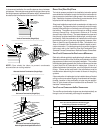
A condensing gas furnace achieves its high level of efficiency by
extracting almost all of the heat from the products of combustion
and cooling them to the point where condensation takes place.
Because of the relatively low flue gas temperature and water con-
densation requirements, PVC pipe is used as venting material.
This furnace must not be connected to Type B, BW, or L vent or
vent connector, and must not be vented into any portion of a fac-
tory built or masonry chimney except when used as a pathway for
PVC as described later in this section. Never common vent this
appliance with another appliance or use a vent which is used by a
solid fuel appliance. Do not use commercially available “no hub
connectors” other than those shipped with this product.