


51
ANNUAL INSPECTION
The furnace should be inspected by a qualified installer, or service
agency at least once per year. This check should be performed at
the beginning of the heating season. This will ensure that all fur-
nace components are in proper working order and that the heating
system functions appropriately. Pay particular attention to the fol-
lowing items. Repair or service as necessary.
• Flue pipe system. Check for blockage and/or leakage.
Check the outside termination and the connections at
and internal to the furnace.
• Heat exchanger. Check for corrosion and/or buildup within
the heat exchanger passageways.
• Burners. Check for proper ignition, burner flame, and
flame sense.
• Drainage system. Check for blockage and/or leakage.
Check hose connections at and internal to furnace.
• Wiring. Check electrical connections for tightness and/
or corrosion. Check wires for damage.
• Filters.
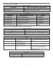
FILTERS
T
O
ENSURE
PROPER
UNIT
PERFORMANCE
,
ADHERE
TO
THE
FILTER
SIZES
GIVEN
IN
THE
RECO MMENDE D
M
INIMUM
F
ILTER
S
IZE
T
ABLE
OR
S
PECIFICATION
S
HEET
APPLICAB LE
TO
YOUR
MODEL
.
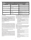
CAUTION
FILTER M AINTENANCE
Improper filter maintenance is the most common cause of inad-
equate heating or cooling performance. Filters should be cleaned
(permanent) or replaced (disposable) every two months or as re-
quired. When replacing a filter, it must be replaced with a filter of
the same type and size.
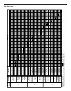
FILTER REMOVAL
Depending on the installation, differing filter arrangements can be
applied. Filters can be installed in either the central return register
or a side panel external filter rack (upflow only). A media air filter or
electronic air cleaner can be used as an alternate filter. Follow the
filter sizes given in the Recommended Minimum Filter size table
to ensure proper unit performance.
To remove filters from an external filter rack in an upright upflow
installation, follow the directions provided with external filter rack
kit.
HORIZONTAL UNIT FILTER REMOVAL
Filters in horizontal installations are located in the central return
register or the ductwork near the furnace.
To remove:
1. Turn OFF electrical power to furnace.
2. Remove filter(s) from the central return register or ductwork.
3. Replace filter(s) by reversing the procedure for removal.
4. Turn ON electrical power to furnace.
MEDIA AIR FILTER OR ELECTRONIC AIR CLEANER REMOVAL
Follow the manufacturer’s directions for service.
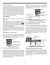
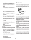
BURNERS
Visually inspect the burner flames periodically during the heating
season. Turn on the furnace at the thermostat and allow several
minutes for flames to stabilize, since any dislodged dust will alter
the flames normal appearance. Flames should be stable, quiet,
soft, and blue (dust may cause orange tips but they must not be
yellow). They should extend directly outward from the burners
without curling, floating, or lifting off. Flames must not impinge on
the sides of the heat exchanger firing tubes.
INDUCED D RAFT AND C IRCULATOR B LOWERS
The bearings in the induced draft blower and circulator blower mo-
tors are permanently lubricated by the manufacturer. No further
lubrication is required. Check motor windings for accumulation of
dust which may cause overheating. Clean as necessary.
CONDENSATE T RAP AND D RAIN S YSTEM (QUALIFIED S ERVICER
ONLY)
Annually inspect the drain tubes, drain trap, and field-supplied drain
line for proper condensate drainage. Check drain system for hose
connection tightness, blockage, and leaks. Clean or repair as
necessary.
FLAME S ENSOR (QUALIFIED S ERVICER O NLY)
Under some conditions, the fuel or air supply can create a nearly
invisible coating on the flame sensor. This coating acts as an
insulator causing a drop in the flame sense signal. If the flame
sense signal drops too low the furnace will not sense flame and
will lock out. The flame sensor should be carefully cleaned by a
qualified servicer using emery cloth or steel wool. Following clean-
ing, the flame sense signal should be as indicated in the Specifica-
tions Sheet.