


47
THERMOSTAT MENU
If this furnace is installed with a communicating compatible heat
pump, the system is recognized as a dual fuel system. The
balance point temperature should be set via the thermostat ad-
vanced menu. Navigate to the THERMOSTAT menu. Press the
INSTALLER CONFIG key. Navigate to the SETUP menu and
press the INSTALLER CONFIG button. See communicating
thermostat installation instructions for additional information.
Navigate to dF BAL PNT. Adjust the dual fuel system balance
point using the back/forward arrows.
DIAGNOSTICS
Accessing the furnace’s diagnostics menu provides ready ac-
cess to the last ten faults detected by the furnace. Faults are
stored most recent to least recent. Any consecutively repeated
fault is stored a maximum of three times. Example: A clogged
return air filter causes the furnace limit to trip repeatedly. The
control will only store this fault the first three consecutive times
the fault occurs. Navigate to the diagnostics menu as described
above in Accessing and Navigating the Advanced Features Menus.
NOTE: It is highly recommended that the fault history be cleared
when performing maintenance or servicing the furnace.
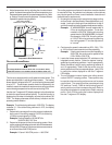
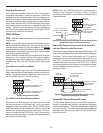
NETWORK TROUBLESHOOTING
The indoor control is equipped with a bank of three dipswitches
that provide biasing and termination functions for the communi-
cations transmission lines. The outdoor control in the commu-
nicating compatible unit is equipped with a bank of two
dipswitches that provide termination functions for the communi-
cations transmission lines. Communications errors will result if
these switches are not correctly set. Note that the ON position
is the correct position for all bias and pull up/pull down
dipswitches.
The ComfortNet™ system is a fully communicating system, and
thus, constitutes a network. Occasionally the need to trouble-
shoot the network may arise. The integrated furnace control has
some on-board tools that may be used to troubleshoot the net-
work. These tools are: red communications LED, green receive
(Rx) LED, and learn button.
• Red communications LED – Indicates the status of the
network. The table below indicates the LED status and
the corresponding potential problem.
• Green receive LED – Indicates network traffic. The table
below indicates the LED status and the corresponding
potential problem.
• Learn button – Used to reset the network. Depress the
button for approximately 2 seconds to reset the network.
SYSTEM T ROUBLESHOOTING
NOTE: Refer to the instructions accompanying the ComfortNet
compatible outdoor AC/HP unit for troubleshooting information.
Refer to the Troubleshooting Codes for a listing of possible fur-
nace error codes, possible causes and corrective actions.
FAULT R ECALL S EQUENCE
• Only allowed in standby mode while display is
showing ON.
• Hold fault recall push-button for 2-5 seconds (until
display is blank) and then release.
• Display will then be blank for 2 seconds before
displaying faults stored in history.
• All faults are displayed one time, from most recent to
least recent.
• A Maximum of 3 consecutive faults of the same type
will be logged.
• Each error is displayed for 2 seconds, with a blank
screen for 1 second in between.
• When all errors have been displayed, the display
returns to ON.
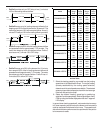
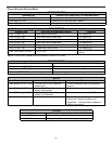
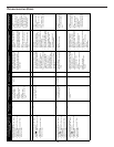
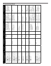
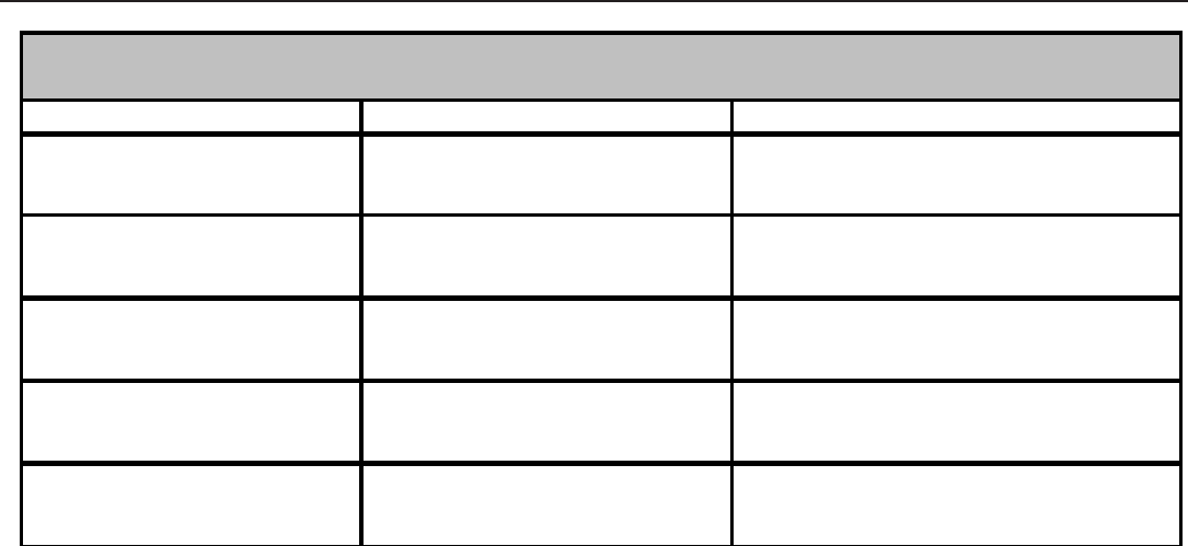
Submenu Item User Modifiable Options Comments
Cool Airflow (CL CFM) 18, 24, 30, 36, 42, 48, or 60, default
is 18
Selects the airflow for the non-
communicating compatible single stage AC
unit
Cool Airflow Trim (CL TRM) -10% to +10% in 2% increments,
default is 0%
Selects the airflow trim amount for the non-
communicating compatible single stage AC
unit
Cool Airflow Profile (CL PRFL) A, B, C, or D, default is A Selects the airflow profile for the non-
communicating compatible single stage AC
unit
Cool ON Delay (CL ON) 5, 10, 20, or 30 seconds, default is
5 seconds
Selects the indoor blower ON delay for the
non-communicating compatible single
stage AC unit
Cool OFF Delay (CL OFF) 30, 60, 90, or 120 seconds, default
is 30 seconds
Selects the indoor blower OFF delay for the
non-communicating compatible single
stage AC unit
NON-COMM (APPLIES ONLY TO A COMMUNICATING COMPATIBLE FURNACE MATCHED
WITH A NON-COMMUNICATING COMPATIBLE SINGLE STAGE AIR CONDITIONER)