


34
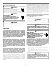
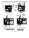
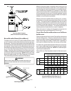
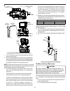
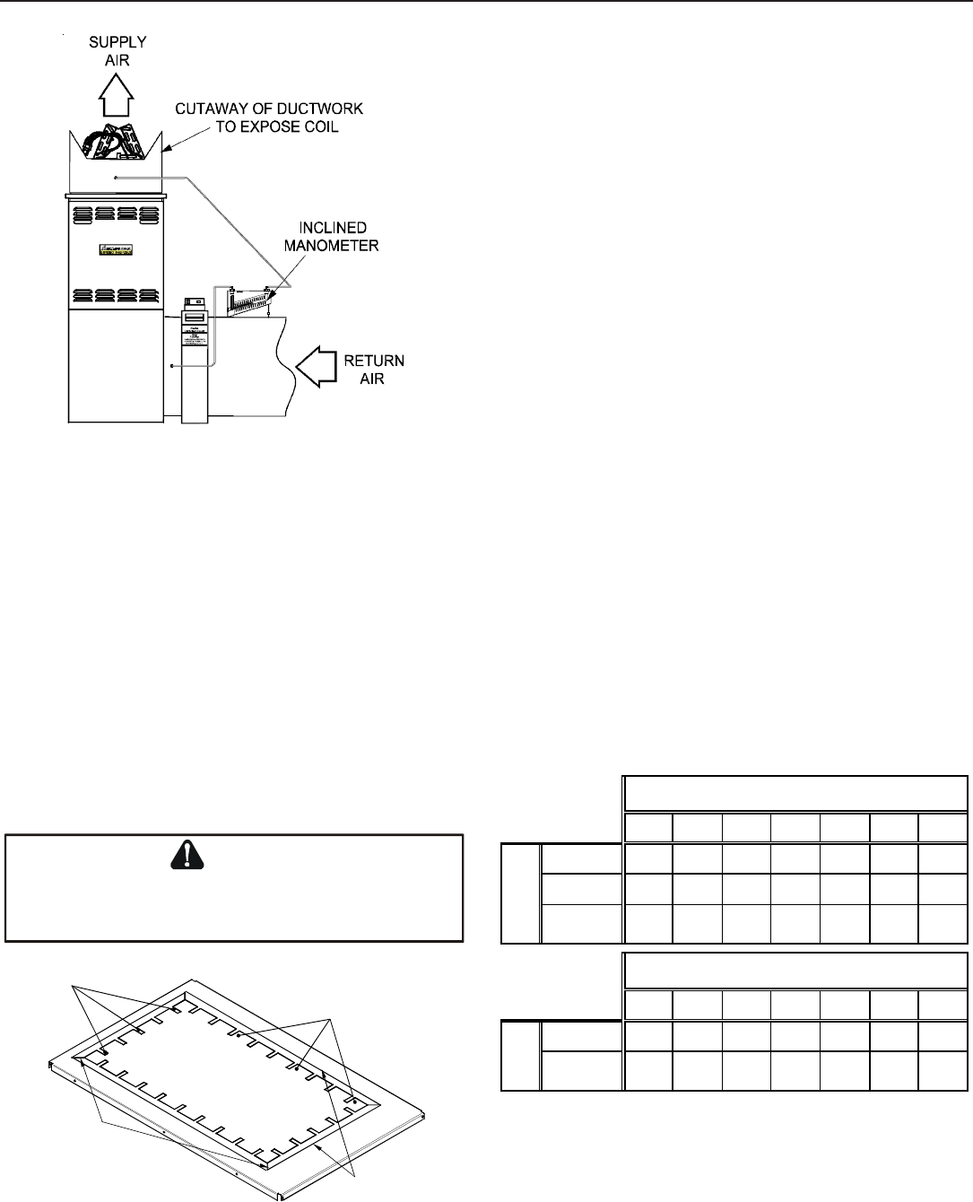
Checking Static Pressure
(80% Furnace Shown, 90% Similar)
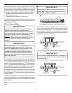
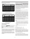
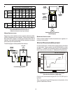
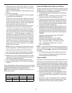
BOTTOM R ETURN A IR O PENING [UPFLOW M ODELS]
The bottom return air opening on upflow models utilizes a “lance
and cut” method to remove sheet metal from the duct opening in
the base pan. To remove, simply press out the lanced sections by
hand to expose the metal strips retaining the sheet metal over the
duct opening. Using tin snips, cut the metal strips and remove the
sheet metal covering the duct opening. In the corners of the open-
ing, cut the sheet metal along the scribe lines to free the duct
flanges. Using the scribe line along the duct flange as a guide,
unfold the duct flanges around the perimeter of the opening using a
pair of seamer pliers or seamer tongs. NOTE: Airflow area will be
reduced by approximately 18% if duct flanges are not unfolded.
This could cause performance issues and noise issues.
E
DGES
OF
SHEET
METAL
HOLES
MAY
BE
SHARP
.U
SE
GLOVES
AS
A
PRECAUTION
WHEN
REMOVING
SHEET
METAL
FROM
RETURN
AIR
OPE NINGS
.
WARNING
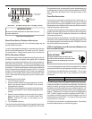
CUT FOUR CORNERS
AFTER REMOVING SHEET
METAL
CUT USING TIN SNIPS
PRESS OUT BY HAND
SCRIBE LINES OUTLINING
DUCT FLANGES
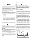
Duct Flange Cut Outs
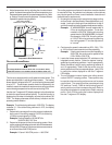
When the furnace is used in connection with a cooling unit, the
furnace should be installed in parallel with or on the upstream side
of the cooling unit to avoid condensation in the heating element.
With a parallel flow arrangement, the dampers or other means
used to control the flow of air must be adequate to prevent chilled
air from entering the furnace and, if manually operated, must be
equipped with means to prevent operation of either unit unless the
damper is in the full heat or cool position.
When the furnace is installed without a cooling coil, it is recom-
mended that a removable access panel be provided in the outlet
air duct. This opening shall be accessible when the furnace is
installed and shall be of such a size that the heat exchanger can
be viewed for visual light inspection or such that a sampling probe
can be inserted into the airstream. The access panel must be
made to prevent air leaks when the furnace is in operation.
When the furnace is heating, the temperature of the return air
entering the furnace must be between 55°F and 100°F.
FILTERS - READ T HIS S ECTION B EFORE I NSTALLING T HE R ETURN
AIR D UCT WORK
Filters must be used with this furnace. Discuss filter maintenance
with the building owner. Filters do not ship with this furnace, but
must be provided, sized and installed externally by the installer.
Filters must comply with UL900 or CAN/ULCS111 standards. If
the furnace is installed without filters, the warranty will be voided.
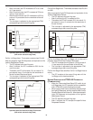
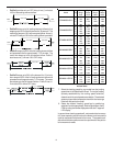
On upflow units, guide dimples locate the side return cutout loca-
tions. Use a straight edge to scribe lines connecting the dimples.
Cut out the opening on these lines. NOTE: An undersized open-
ing will cause reduced airflow.
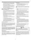
Refer to Minimum Filter Area tables to determine filter area require-
ments.
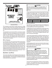
600 800 1000 1200 1400 1600 2000
0603__XA --- --- 627* 627* 672 768 ---
0805__XA --- --- --- 836* 836* 836* 960
1005__XA
1155__XA
--- --- --- 940* 940* 940* 960
600 800 1000 1200 1400 1600 2000
0604__XA --- --- 320* 320* 336 384 ---
0805__XA
1005__XA
--- --- --- 427* 427* 427* 480
Input
Airflow
UPFLOW
COOLING AIRFLOW REQUIREMENT (CFM)
COUNTERFLOW
COOLING AIRFLOW REQUIREMENT (CFM)
Input
Airflow
*Minimum filter area dictated by heating airflow requirement.
Permanent Minimum Filter Area (sq. in)
[Based on a 600 ft/min filter face velocity]