


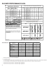
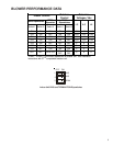

BLOWER PERFORMANCE DATA
8
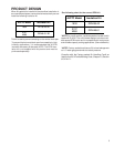
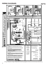
C ------- 7.5 min/82% 60 sec/100%
Profiles Pre-Run Short-Run OFF Delay
To set Comfort Mode:
B ------- 30 sec/50% 60 sec/100%
Speed Selection Dip Switches
0140A00048 REV A
A OFF OFF OFF OFF OFF OFF
D 30 sec/50% 7.5 min/82% 30 sec/50%
To set airflow:
TAP 1 2 3 4 5 6
B ON OFF ON OFF ON OFF
A ------- -------- 60 sec/100%
Select desired Comfort Mode profile
(see profiles above). Set switches 5 and 6 to the approriate
ON / OFF positions.
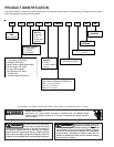
(1) Select model and desired
high stage cooling airflow. Determine the cooresponding tap
( A, B, C, or D ). Set dip switches 1 and 2 to the appropriate
ON / OFF positions. (2) Select model and installed electric
heater size. Set switches 9, 10, and 11 to the appropriate
ON/OFF positions. (3) Select the airflow adjustment factor tap
A and D are 0%; Tap B is +10%; Tap C -10%. Set dip switches 3
and 4 to the appropriate ON / OFF positions.
C OFF ON OFF ON OFF ON
D ON ON ON ON ON ON
Cool Adjust Profile
Selection Selection Selection
Switches Switches Switches
20 OFF OFF ON NR NR 1600
15 OFF ON OFF NR 1400 1400
10 OFF ON ON 1200
1200
1200
8 ON OFF OFF 1000 1000 1000
6 ON OFF ON 800 800 800
5 ON ON OFF 700
700 700
3 ON ON ON 600 600 600
Htr Kw 9 10 11 AVPTC 183014*
AVPTC 313714* AVPTC 426014
*
21 OFF OFF OFF NR NR 1600
C ------- 7.5 min/82% 60 sec/100%C ------- 7.5 min/82% 60 sec/100%C ------- 7.5 min/82% 60 sec/100%
B ------- 30 sec/50% 60 sec/100%B ------- 30 sec/50% 60 sec/100%B ------- 30 sec/50% 60 sec/100%
D 30 sec/50% 7.5 min/82% 30 sec/50%D 30 sec/50% 7.5 min/82% 30 sec/50%D 30 sec/50% 7.5 min/82% 30 sec/50%D 30 sec/50% 7.5 min/82% 30 sec/50%
To set airflow:
(1) Select model and desired
To set airflow:
(1) Select model and desired (1) Select model and desired
high stage cooling airflow. Determine the cooresponding tap
high stage cooling airflow. Determine the cooresponding tap
( A, B, C, or D ). Set dip switches 1 and 2 to the appropriate
ON / OFF positions. (2) Select model and installed electric
A 810 1210
C 1047 1562
D 1209 1804
A 409 610
B 553 825
C 696 1040
D 829 1237
A 422 630
B 563 840
C 694 1036
D 825 1232
AVPTC 183014
*
Model Tap Low Stage High Stage
Cool Cool
AVPTC 313714
*
AVPTC 426014
*
A 409 610A 409 610A 409 610
B 553 825
B 553 825B 553 825
C 696 1040
C 696 1040C 696 1040
A 422 630
A 422 630A 422 630
B 563 840
B 563 840B 563 840
C 694 1036
C 694 1036C 694 1036
D 825 1232
D 825 1232D 825 1232
AVPTC 183014
*
AVPTC 313714
*
Electric Heat Airflow and Temperature Rise Table
Cooling/Heat Pump Airflow Table
NOTE: Airflow data shown applies to the emergency heat mode (electric heat only)
in either legacy mode operation or fully communicating mode operation.
MODELS AVPTC183014A* AVPTC313714* AVPTC426014A*
HKR-03* X X X
HKR-05*/-05C* X X X
HKR-06* X X X
HKR-08*/-08C* X X X
HKR-10*/-10C*
X
1
XX
HKR-15C
X
2
X
HKR-20C
X
3
HKR-21C
X
3
Heat Kit Selection
* Revision level that may or may not be designated.
C Circuit breaker option.
1
For units operating in Legacy mode, use dip switches 9-ON, 10-OFF, 11-OFF, to obtain 1000 CFM, or 9-OFF, 10-ON, 11-ON to obtain 1200 CFM.
For units operating in Communicating mode, use dip switch 8 kW Htr to obtain 1000 CFM or 10 kW Htr to obtain 1200 CFM.
2
This heater kit can only be used for ‘1000 CFM or higher’ applications.
3
This heater kit can only be used for ‘1200 CFM or higher’ applications.