


6
Safety instructions
NOTE: In the event of leaks in the water pipework close the
main cold water stop valve. This is often located under a
kitchen sink.
IMPORTANT: A thermostatic mixing valve must be tted to
the outlet of the cylinder and can be adjusted to the desired
domestic hot water temperature by an installation or service
engineer. Otherwise there is a risk of scalding as the cylinder
outlet temperature at the taps could be up to 85°C.
IMPORTANT: Risk of damage! Do not remove or modify any
components of the solar cylinder.
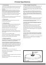
In the unlikely event of a malfunction occurring of the Flurocyl,
such as hot water owing out of the temperature and pressure
relief valve, switch off the boiler and the immersion heater and
contact Glow-worm or your installer.
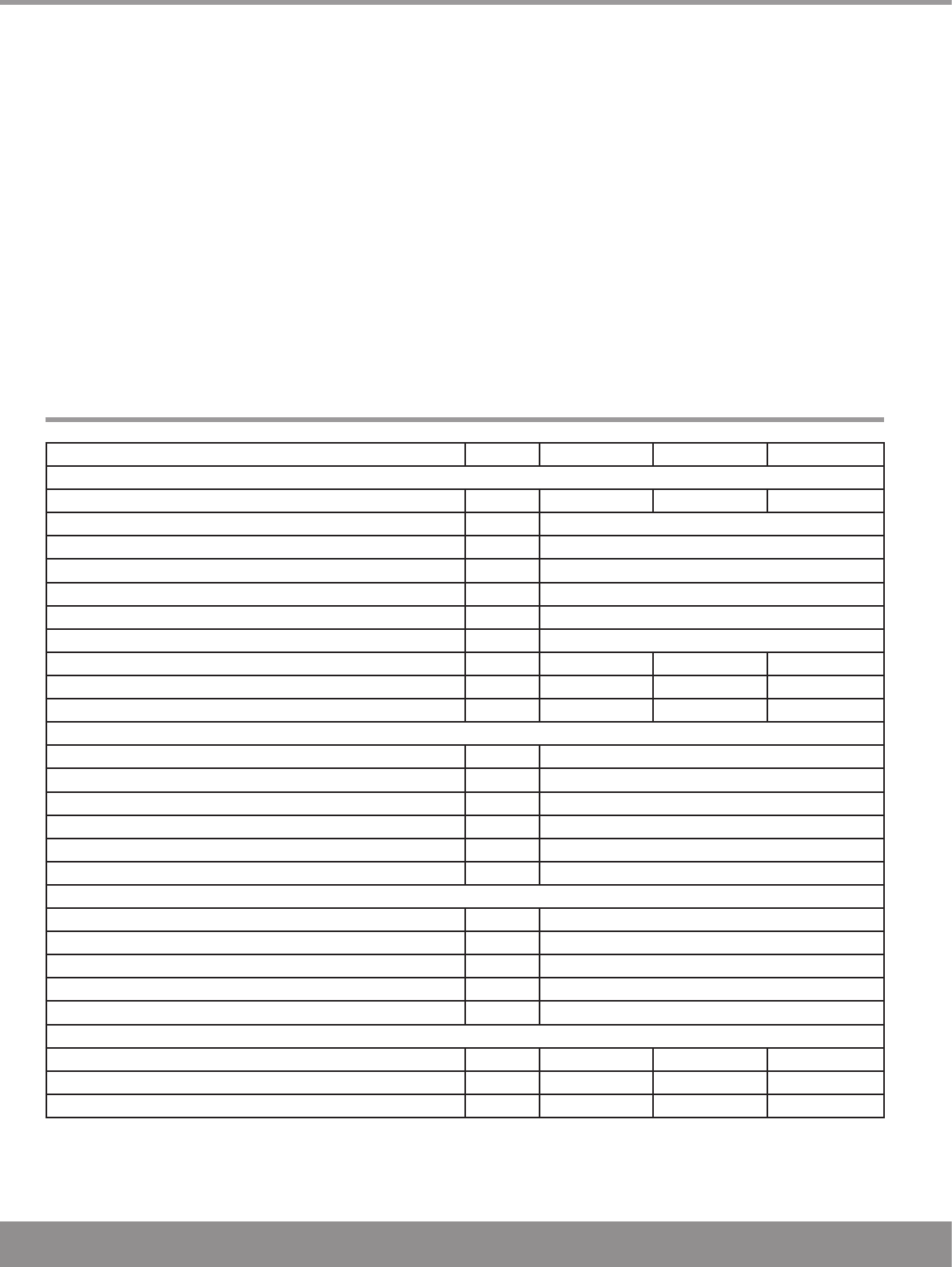
Safety Instructions
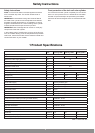
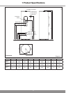
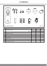
Unit Flurocyl 200 l Flurocyl 250 l Flurocyl 300 l
Cylinder:
Size l 200 250 300
Maximum water supply pressure bar 10
Operating pressure bar 3.5
Pressure limiting valve bar 3.5
Expansion relief valve bar 6.0
Hot water expansion vessel admission pressure bar 4.0
Temperature and pressure relief valve °C/bar 95 / 7.0
Net weight kg 39 44 49
Weight (full) kg 245 310 340
Height mm 1499 1789 2109
Cylinder connections:
Cold water supply 22 mm pressure pipe
Hot water connection 22 mm pressure pipe
Pressure-controlled cold water outlet 22 mm pressure pipe
Secondary return Inches G 3/4
Flow (boiler/solar circuit) 22 mm pressure pipe
Return (boiler/solar circuit) 22 mm pressure pipe
Electrical connections:
3 kW immersion heater (according to ENBS 60335) 230/240 V, 50 Hz
Length of the immersion heater mm 430
Motorised 2 port valve 230/240 V, 50 Hz
Cylinder thermostat 230/240 V, 50 Hz
Thermal cut out for solar pump 230/240 V, 50 Hz
Heating coil:
Heat loss kW/24 h 1.9 2.1 2.4
Heat up time (boiler part) mins 21 26 30
Recovery (boiler part) mins 13 16 21
Table 1.1 Technical data
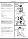
Frost protection of the twin coil solar cylinder
You must drain the solar cylinder completely if it is to be shut
down in a room prone to frost. It is drained at the cold water
inlet with a T-piece with tap to be provided by the installer.
Also drain all heat exchangers which are not lled with solar
uid.
1 Product Specications