


16
2 Installation
2.10 Electrical installation
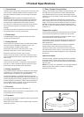
Remove the front fascia panel.
Wiring should be performed by a competent person in
accordance with the building regulations, Part P of the
current IEE regulations and further applicable regulations and
directives.
The discharge pipes of the tundish, drain valves, motorised
valves etc. should be laid at a safe distance to electrical
components.
IMPORTANT: Danger of death from electric shock! You must
earth the solar cylinder for potential equalisation.
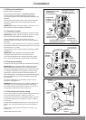
2.11 Immersion heater
The Flurocyl solar cylinders incorporate an immersion heater.
IMPORTANT: Danger of death from electric shock! You must
earth the immersion heater for potential equalisation.
Install a separate electrical power supply line for the
immersion heater in accordance with current IEE regulations
(BS 7671).
You must lay a heat-resistant line (3 x 2.5 mm
2
) from a double
pole isolating switch for the immersion heater. The circuit must
be protected by a 13 A fuse.
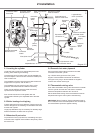
The connection of the immersion heater is illustrated in detail
in diagram 2.7.
IMPORTANT: Risk of damage! The immersion heater
is equipped with a thermal cut out and may under no
circumstance be replaced by a standard immersion heater.
Only correct original Glow-worm spare parts are permitted.
2.12 Thermostat setting
The entire inner wiring has been pre-assembled at the factory.
IMPORTANT: Risk of damage! Switch off the power supply
before resetting the thermal cut out or making any other
changes to the temperature setting of the cylinder thermostat.
The cylinder thermostats for the regulation of the hot water
temperature are factory set at 65°C as the Domestic Hot
Water temperature is controlled by the adjustable thermostatic
mixing valve.Ensure both control thermostats are adjusted
fully clockwise.
Actuate the reset buttons, to reset the thermal cut outs if
necessary, see diagram 2.7.
IMPORTANT: Risk of damage! If the immersion heater is not
connected, you must connect the earth wire to terminal E
on the terminal strip of the immersion heater. You can nd a
wiring sheme on the inside of the cylinder cover.
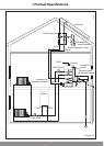
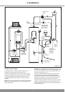
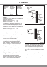
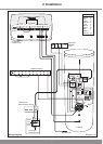
2.13 Thermostat and sensor wiring
Connect the domestic hot water demand wiring to the reheat
control thermostat as shown in diagram 2.8 and 2.10.
Connect the solar pump live via the solar thermal cut out and
ensure this thermal cut out is earthed, as shown in diagram
2.8. and 2.10.
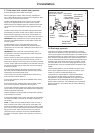
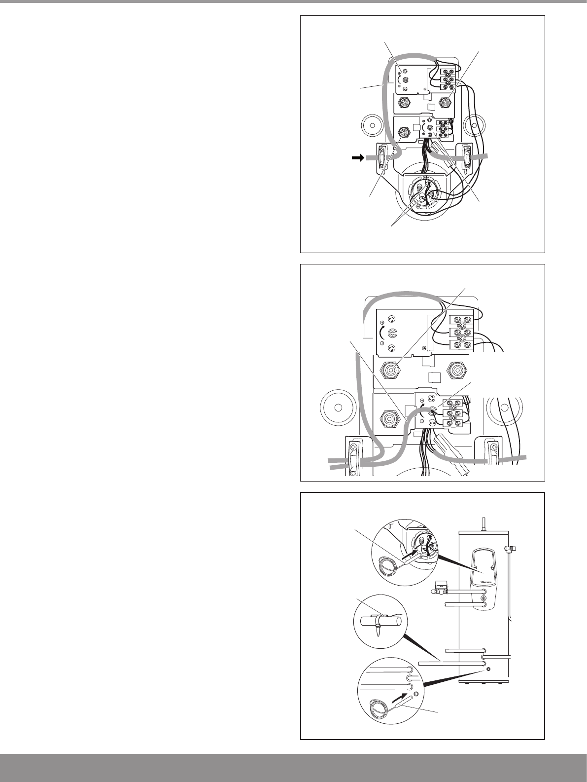
Install the two temperature sensors in the solar cylinder, see
diagram 2.9, and connect to the solar control, see diagram
2.10.
Attach the solar gain sensor to the solar circuit return, see
diagram 2.9.
Replace the front fascia panel.
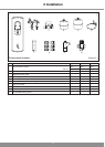
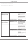
IMMERSION HEATER
THERMAL CUT OUT
WITH RESET BUTTON
REHEAT
THERMAL
CUT OUT WITH
RESET BUTTON
REHEAT
THERMOSTAT
(FACTORY SET)
IMMERSION HEATER
THERMOSTAT
(FACTORY SET)
IMMERSION
HEATER
CONNECTION
230V AC 3 kW
TEMPERATURE SENSORS
IN IMMERSION SLEEVES
230V
AC
3 kW
30°
4
0
°
5
0
°
65°
30°
4
0
°
5
0
°
65°
LN
1 2 3
Diagram 2.7
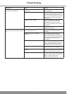
14190
14192
Diagram 2.9
14194
UPPER
TEMPERATURE
SENSOR
LOWER
TEMPERATURE
SENSOR
TEMPERATURE
SENSOR
GAIN
3
0
°
40
°
50°
65°
3
0
°
40°
50°
65°
LN
1 2
3
DOMESTIC
HOT WATER
DEMAND
WIRING
REHEAT
CONTROL
THERMOSTAT
(FACTORY SET)
SOLAR THERMA
L
CUT-OUT WITH
RESET BUTTON
Diagram 2.8