


15
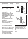
Minimum diameter
of the discharge
pipe from the
tundish
Maximum
permissible
total resistance,
expressed as
straight pipe
length (without
elbows or bends)
Resistance due
to each elbow
or bend (straight
length equivalent)
22mm
Up to 9m 0.8m
28mm Up to 18m 1.0m
35mm Up to 27m 1.4m
Table 2.2 Resistance
Examples:
22mm discharge pipe with 4 elbows and of 7m length from the
tundish to the discharge point:
Resistance for 4 elbows per 0.8m = 3.2m
Resistance for discharge pipe = 7.0m
Total resistance = 10.2m
The total resistance of the discharge pipe is higher than the
maximum permissible value for 22mm pipes (9m). Base your
calculations therefore on the next largest pipe diameter.
28mm discharge pipe with 4 elbows and of 7m length from the
tundish to the discharge point:
Resistance for 4 elbows per 1.0m = 4.0m
Resistance for discharge pipe = 7.0m
Total resistance = 11.0m
The total resistance of the discharge pipe is lower than the
maximum permissible value for 28mm pipes (18m),which
means this pipe diameter can be used.
Water which is almost boiling may escape from the discharge
pipe in the event of an error.
IMPORTANT: Risk of being scalded by escaping hot water!
Make sure the discharge pipe ends at a safe point inside or
outside the building (safe and visible), where there is no risk
of anyone coming in contact with hot water.
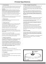
A suitable point is, for example, under a xed grating above
the trap of a trapped gully. Low discharge pipes, for example
up to 100mm above external surfaces, such as parking
spaces, grasslands etc., can be used, provided they are
secured by a wire fence or something similar to prevent
children from coming in contact with the waste water, and the
system is visible. No valves or taps may be installed in the
discharge pipe.
Make sure the discharge pipe is at a constant slope of at least
1:200 from the tundish to the discharge point.
The discharge pipe from the pressure relief valve of the boiler
(if applicable) can be connected to the horizontal discharge
pipe of the solar cylinder behind the tundish with a T-piece.
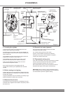
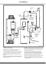
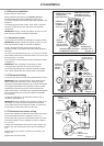
2.9 High level discharge termination
Providing that the point of termination is such that persons
in or around the building will not be endangered should
discharge take place, this method of termination is
satisfactory. Points to consider when deciding whether a
location for the high level of discharge is suitable are:
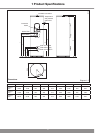
METAL DISCHARGE PIPE FROM
TEMPERATURE RELIEF VALVE
TO TUNDISH
METAL DISCHARGE PIPE
FROM TUNDISH WITH
CONTINUOUS FALL
TUNDISH
DISCHARGE
BELOW
FIXED
GRATING
FIXED
GRATING
TRAPPED GULLY
SAFETY DEVICE
(E.G. TEMPERATURE
RELIEF VALVE
VENTIL)
500 MM
MINIMUM
300 MM
MINIMUM
Diagram 2.5
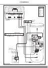
14188
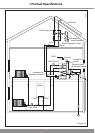
TUNDISH
300 MM
MINIMUM
DISCHARGE
PIPE
METAL
HOPPER
HEAD
Diagram 2.6
14189
The possibility, taking into account wind effect, that someone
may be in the path of the water being discharged and if so,
whether the temperature of the discharge water will have
been sufciently reduced to not be dangerous. Thermal
conductivity of the structure's surface, climatic conditions and
location and orientation of the discharge pipe may or may not
have an effect on reducing the temperature of the discharge
water.
The location of windows and similar openings.
The likelihood of a pram being left beneath the point of
discharge.
The ability of structures surface to withstand near boiling
water.
The possibility of ice formation if water is discharged onto
pedestrian walkways.
2 Installation