


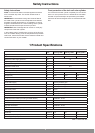

14
2 Installation
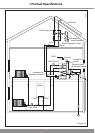
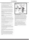
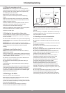
2.7 Cold water inlet controls and pipework
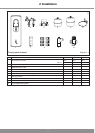
Connect both parts of the water control pack.
When installing the valves, make sure they are aligned in
such a way that the 15mm connection of the expansion relief
valve can be connected to the tundish.
Install the assembled water control pack in the cold water
supply at an appropriate place next to the solar cylinder.
Make sure there is sufcient space for maintenance and the
connection of the discharge pipe from the expansion relief
valve.
Install the drain valve in the cold water supply at the lowest
point between the solar cylinder and the water control pack.
We recommend applying a hose, which reaches about 1m
under the base of the cylinder, to the outlet of the drain valve.
IMPORTANT: Risk of bursts for the solar cylinder! No stop
valve may be installed between the cold water control pack
and the cylinder.
Install the water pack so that a discharge pipe of the
expansion relief valve can be tted with constant outward
slope which can end at a safe, visible point where there is no
risk of freezing.
IMPORTANT: Risk of the solar cylinder bursting due to
overpressure! The outlet of the expansion relief valve must
not be covered or closed.
Test the expansion relief valve regularly to avoid calcication.
To ensure an optimum performance of the solar cylinder, in
particularly buildings in which a pressure controlled cold water
is used, copper pipes with a diameter of at least 22mm should
be used for the pipe from the main stop valve of the building
to the solar cylinder.
If the discharge pipes are all together, the expansion relief
valve may not be installed more than 500 mm away from the
temperature and pressure relief valve.
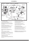
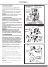
The Flurocyl solar cylinder is supplied with an external hot
water expansion vessel (DW EV).
Connect this expansion vessel to the installed water control
pack as follows:
Screw the expansion vessel directly onto the water control
pack, via the connection intended for this purpose or
Connect the expansion vessel to the water control pack with a
copper pipe or an appropriate hose. Make sure the expansion
vessel is supported sufciently.
Use the supplied mounting bracket if the expansion vessel is
to be mounted on the wall.
Connect thermostatic mixing valve cold supply to the pressure
controlled cold water connection of the water control pack (if
convenient).
NOTE: In areas with high water pressure (4 bar or more), a
bath or shower mixer valve could also be connected to the
pressure-controlled cold water connection of the water control
pack. This is to ensure the pressure of the hot and cold water
supply to the mixer valve is about the same. Any second
cold water supply connection should be installed between
the water control pack and the solar cylinder by means of a
T-piece.
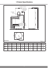
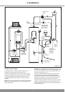
COLD
WATER
SUPPLY
PRESSURE LIMITING
VALVE WITH LINER
STRAINER
BALANCED
PRESSURE
COLD WATER
CONNECTION
HOT WATER
EXPANSION
VESSEL
CONNECTION
EXPANSION
RELIEF VALVE
FLUROCYL
CONNECTION
LEGIONELLA
LOOP
CONNECTION
Diagram 2.4
14187
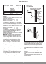
2.8 Discharge pipework
The outlet connections of both the temperature / pressure
relief valve and expansion relief valve should be connected in
15mm copper pipe to the tundish supplied. The tundish should
be installed vertically, as close to the Flurocyl as possible and
within 500mm of the temperature and pressure relief outlet. It
must be positioned away from any electrical components and
installed in the same space as the Flurocyl cylinder, so that
it is visible to the user. The D1 discharge pipe from the T&P
Valve/Expansion valve can be teed together upstream of the
tundish.
The discharge pipework must be installed using minimum
22mm copper pipework from the 22mm connection on the
tundish to a safe and visible discharge point.
There must be a vertical section of pipe at least 300mm
long, below the tundish before any bends or elbows in
the pipework. Increase the diameter of the pipework if the
total resistance of the discharge pipework exceeds the
gures shown in table 2.2. The installation of the discharge
pipework must be in accordance with G3 refer to Statutory
Requirements.