


2
NOTE: Contact Giant Industries for Service School Information. Phone: (419)-531-4600
INSTALLATION INSTRUCTIONS
Installation of the Giant Industries, Inc., pump is not a complicated procedure, but there are some basic steps common to all
pumps. The following information is to be considered as a general outline for installation. If you have unique requirements,
please contact Giant Industries, Inc. or your local distributor for assistance.
1. Set-Up and Installation
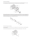
The pump is to be mounted horizontally onto a solid frame that is also to accommodate the drive motor. The place of
installation has to be chosen so that the belt drive and pump are made easily accessible for maintenance work (oil dip
stick and oil filler plug must also be easy to reach.)
1.1 Pump
Important! The preferred drive form is with toothed belts. Bare V-belts are admissible if the exact required belt tension can be
kept. Excessive belt tension can lead to increased heating of the drive system, and can even lead to breakage of the crank-
shaft.
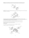
Important! The direction of rotation of the pump is indicated by an arrow on both bearing flanges situated of the crankcase.
The indicated direction of rotation must be observed to ensure that gear parts are properly lubricated.
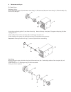
1.1.1 Hydraulic Connections
a.) Inlet Line
· On both sides of the pump head there is one ½ suction port and one 3/8 discharge port. Non-required portholes can
be closed with the supplied plugs and bonding agent.
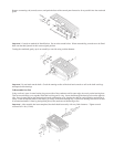
· Suction and discharge connections are to be fitted with elastic tubes to damp vibrations and guard the pump against
pipeline tensions.
· The diameter of the suction line must be at least one size bigger than the suction inlet port.
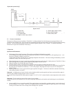
Important! The pump is not to be connected directly to the water mains as gas bubbles present in fresh water can lead to
premature wear and destruction of seals and valves.
A feed tank with a volume at least 5 times greater than the pump discharge rate per minute is to be installed.
The feed tank must be fitted with baffle plates to stop any air coming into the tank from passing on through the suction port.
· The necessary input pressure of 36.0 PSI (2.5 Bar) bar must be guaranteed using a centrifugal pump. A filter (max. particle
size 50 micron) with a volume at least 3 times greater than the pump discharge rate per minute must be fitted between the
centrifugal pump and high pressure pump. To check the required input pressure, we recommend the installation of a
pressure gauge between the filter and high pressure pump.
Important! All fittings must be tightly fixed to avoid air entering into suction line. To avoid dirt entering into the pump head,
the suction line should be thoroughly rinsed before being fixed to the suction port.
b.) Discharge Line
· Tubes, pipes and fittings of the discharge line must have a safety factor well above the maximum operating pressure.
· A suitable safety valve must be installed immediately after the initial length of flexible discharge line.
There are to be no shut-off valves between the pump and safety valve.
· An air vent should be built into the discharge line as near as possible to the pump.
· The most optimal place for installing a pressure gauge is between the pump and safety valve. The second outlet on the
pump casing can also be used for this purpose.
· The discharge line is to be laid either horizontally or rising steadily away from the pump.
· Return-flow lines from unloader valves and safety valves must be connected to the feed tank, never directly to the
suction port.
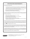
Finally, remember that high pressure operation in a pump system has many advantages. But, if it is used carelessly and without regard
to its potential hazard, it can cause serious injury.