


7. Examine the rubber O-ring on the mechanical seal holder and, if the O-ring is
damaged, replace it with a new one. A new O-ring is included with the facto-
ry-supplied Mechanical Seal Replacement Kit (Section 10.3). Be sure to lubri-
cate with grease before installing.
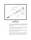
8. Place the mechanical seal holder containing the new stationary seat onto the
pump shaft and slide it down the shaft until fully engaged with the motor
adapter. Care must be taken not to damage seal seat when sliding over the
pump shaft.
9. Lubricate the round surface of the pump shaft with grease. After lubrication,
replace the rotary portion of the mechanical seal by placing onto the pump
shaft and carefully rotating and pushing it down the pump shaft until it is fully
seated against the stationary portion of the mechanical seal.
W
ARNING: USE CARE WHEN SLIDING THE ROTARY PORTION OF THE
MECHANICAL SEAL OVER THE RETAINING RING GROOVE IN
THE PUMP SHAFT. THE RUBBER ON THE MECHANICAL SEAL
CAN BE DAMAGED IF NOT LUBRICATED WITH GREASE.
10. Place the stainless steel retaining ring back onto the shaft to hold the rotary
portion of the mechanical seal in place with the square edges of the retaining
ring away from the seal spring. A retaining ring is included in the factory sup-
plied mechanical seal replacement kit. Use of retaining rings that are not
stainless steel or equivalent may cause the seal to fail in operation.
11. Be sure the retaining ring is properly seated in the groove on the pump shaft.
12. Firmly grasp the liquid end and insert the splined pump shaft into the liquid
end by carefully rotating the liquid end clockwise and then counterclockwise
while applying light pressure toward the motor adapter. Be sure the splined
shaft and splined bore of each impeller meshes properly until the inlet casting
mates with the mechanical seal holder. It may be necessary to lift the assem-
bly up slightly when rotating it, then place it onto the splined shaft.
W
ARNING: CARE MUST BE TAKEN NOT TO BEND THE PUMP SHAFT OR TO
FORCE THE SHAFT INTO THE IMPELLER BORE.
13. Install the four (4) 5/16-inch bolts and lock washers and tighten.
4.4 High-Pressure Mechanical Seal Replacement: SS500, SS1000 and SS1800 Series
Pumps
High pressure mechanical seals have the same basic design as standard mechanical
seals. Replace them using the same procedure as denoted in Section 4.3 (Mechanical
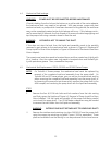
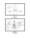
Seal Replacement SS500, SS1000 and SS1800 Series Pumps), Figure 4.6 (Removal of
Mechanical Seal Holder from Motor Adapter), and Figure 4.7 (Removal of Mechanical
Seal from Pump Shaft and Cavity of Mechanical Seal Holder).
16