


3.6 Motor Wiring
3.6.1 Single-Phase Motors
When initially connecting to the power source, be certain that the motor volt-
age connections and available line voltage are the same. Connect electrical
wires as shown on the motor wiring diagram located on the motor name-
plate, electrical junction box, junction box cover, or wiring tag. Be sure your
pump is electrically grounded at the junction box on the motor.
3.6.2 Three-Phase Motors
The wiring diagram located on the motor nameplate, electrical junction box,
junction box cover, or wiring tag should be used to correctly wire the motor
according to the line voltage available. Be sure your pump is electrically
grounded at the junction box on the motor.
CA
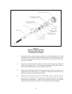
UTION: The 500X, 1000X and 1800X motor adapter pumps have a
threaded motor shaft. Reverse operation can damage the
motor shaft, pump shaft, or centrifugal stages.
Before S
tarting Three-Phase Motors:
STEPS
1. Prime pump before applying power to avoid damage to the pump.
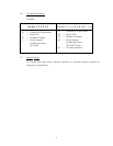
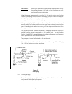
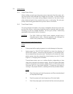
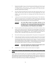
2. Apply power for ONE SECOND MAXIMUM to check the direction of
motor shaft rotation. The motor shaft should turn in a clockwise direc-
tion as viewed from the motor end. The direction of rotation for three-
phase motors may be reversed by interchanging any two (2) leads
(Figure 3.3, Changing Motor Rotation).
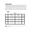
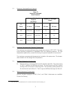
Three-phase motors can run in either direction, depending on how
they are connected to the power supply. When the three cable leads
are first connected to the power supply, there is a 50% chance that
the motor will run in the proper direction. To make sure the motor is
running in the proper direction, carefully follow the procedure below.
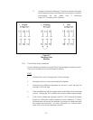
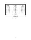
STEPS
A. Start the pump and note the pressure and flow rate developed
at the pump discharge.
B. Stop the pump and interchange any of the two leads.
C. Start the pump again and recheck the flow rate and pressure.
9