


3.0 PUMP INSTALLATION
3.1 Inspection
Your pump was inspected and tested at the factory prior to shipment to ensure it
meets the requirements of your order. It is suggested the pump be checked upon
receipt for possible damage due to shipping. Any damage should be immediately
reported to the carrier.
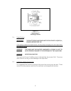
3.2 Pump Mounting and Location
The pump is supported by the motor base, and on longer pumps, a support at the dis-
charge end. The X, XB, and XC motor adapter pumps may be mounted and operated
in either a horizontal or vertical position. The vertical position requires the motor to
be up.
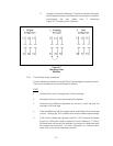
The inlet casting may be rotated to any of four positions by removing the four (4) bolts
on the inlet casting, turning the inlet casting to the desired position and replacing the
4 bolts.
When mounting the pump, be sure the pump casing support and motor base are in
line and on the same plane so that no stress results in the pump after fastening down.
CA
UTION: The inlet and discharge piping should be independently supported.
3.3 Inlet and Discharge Piping and Connections
3.3.1 Inlet Piping
THE INLET PIPING AND PUMP MUST BE FILLED WITH LIQUID
(i.e., PRIMED) BEFORE START-UP. A pressure/vacuum gauge installed in the
inlet piping to measure positive or negative pressure is recommended. Be
sure the pump is not mounted above the liquid source and the inlet (suction)
plumbing not restricted so adequate suction pressure is available.
The inlet piping should be at least as large as the pump inlet port. The dis-
charge piping should be sized to properly handle the maximum flow and pres-
sure developed by the pump.
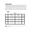
The recommended pipe size for most applications should result in frictional
line loss of 5 psig/100 feet (0.34 barg/100 meters) or less for suction lines and
10 psig/100 feet (0.7 barg/100 meters) or less for discharge lines. A larger pipe
size will reduce the frictional line loss.
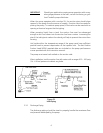
The pump inlet piping should be designed to avoid areas where air may be
trapped and accumulate. Keep the inlet pipe free of high points, which could
trap air and could disrupt pump priming and start-up. Pump inlet pipe size
changes just ahead of the pump should be tapered. Reducers should be
eccentric to avoid air pockets.
5