


DEH40212 Installation Instructions
5
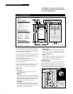
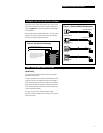
HARDWIRE LOW-VOLTAGE SWITCHES (OPTIONAL)
Each of the ProSys panel’s eight channels has a single switch
input which will accept any of the dry-contact configurations
shown in Figures 6 and 7, and also provides status feedback
for that channel.
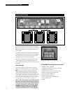
ProSys panels whose catalog numbers end in “P” also include
inputs for each relay. Like the channel inputs, these support
all of the dry-contact configurations shown.
MAINTAINED
ISOLATED CONTACT
RED/BLACK JUMPER
BLACK/WHITE JUMPER
2-WIRE MOMENTARY
PUSH BUTTON
STANDARD 3-WIRE
MOMENTARY
STANDARD 3-WIRE
MAINTAINED
R B Y W
R B Y W
R B Y W
R B Y W
Panel Testing
The panel-to-panel dataline should be tested for continuity
and isolation from ground.
To test for continuity, remove the red and black dataline wires
at panel 01 and wire nut together (short the wires together).
Go to the last panel in the series and measure the resistance
between the red and black terminals. It should be less than 3
ohms. Return to panel 01 and restore the red and black wires
to their associated terminals.
For shorts, test from red to white and black to white
anywhere in the low-voltage section of the panel. You should
see an open circuit.
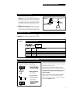
Figure 7 – Hardwired Switch Configurations
Figure 6 – Hardwired Switch Inputs
PANEL TESTING AND TROUBLESHOOTING
HARDWIRED CHANNEL SWITCHES
HARDWIRED RELAY SWITCHES*
* The ability to hardwire a 2- or 3-wire
switch directly to a relay is an option in
ProSys system panels. For panels with relay
inputs, order interiors with catalog
numbers ending in P.