


2
DEH40212 Installation Instructions
J2
1
1
5
V
A
C
N
E
U
G
R
D
G
E
L
ig
h
t
in
g
C
o
n
t
r
o
ls
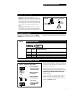
RELAY PANEL INSTALLATION
CAUTION: Make sure all power is OFF before wiring.
Do not energize wiring until the unit is fully assembled.
Conform to all applicable codes.
ILLUSTRATION NOT TO SCALE
If you have purchased the ProSys II Lighting Control System
(the stand-alone system), the devices (panels, switches and
clock) will be in self-install mode, which means that as soon
as they are connected to the network, they are operational
and can communicate with each other.
If you have purchased the ProSys LM Lighting Control System
along with the ProSys LM software, the devices will be in
software-install mode. This means that in order for them to
function on the network you must:
• assign network addresses to the devices and
• bind network variables and message tags using your
network management tool.
Addresses and binding are necessary for the devices to function on
the network. ProSys LM users please refer to the ProSys LM
Software User Guide for instructions on installing devices.
Rough-In Tub
• Environment
32 to 131
o
F (0 to 50
o
C), 0 to 95% relative humidity,
stationary applications
• Mounting
The tub should be level, plumb and rigidly installed with
hardware sufficient to hold 100 lbs. (48kg). For flush-mount
panels, the front flange should be flush with the final
finished surface. For multiple panels, allow
1
⁄4” minimum
between panels for showbox cover clearance.
• Pulling Wires
Route line-voltage wiring through the 2
1
⁄2” knockouts in
either the top or bottom of the tub. Route Class 2 low-
voltage dataline from the remote switches or other controls
through the
3
⁄4” knockouts in either end.
Install Interior
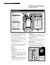
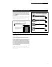
• Power Supply
Attach the power supply to the frame (bottom of 12-relay
interior and left side of 24- or 48-relay interiors) and plug
the low-voltage connector to the terminal marked “POWER”
as shown in Figure 1 above.
• Interior
Mount the interior in the tub and secure it to the studs with
the hardware provided. Make sure that all line- and low-
voltage wiring is confined to the appropriate areas.
Wire Line Voltage
Before making any connections to the relays, make sure that
none of the load circuits are shorted. Wire from the circuit
breaker through each relay’s SPST output terminals, and from
there to the loads. Confirm that each circuit is wired to the
relay specified in the drawings. Wire the power supply.
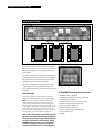
RINTER2424PS
shown
B
A
CC
2" TYP.
SWITCHED LIGHTING CIRCUITS
CLASS 2
LOW-VOLTAGE
WIRING SECTION
LINE-VOLTAGE WIRING SECTIONS
5" WIDE
1.5" x 1.5" CROSSOVER WIRING CHANNEL (TOP AND BOTTOM)
CIRCUIT BREAKER PANEL
RELAYS RELAYS
DIN RAIL
4.5" D
Dimensions (A x B)
RINTER1212PS(P)
16.0" (406mm) x 16.5" (419mm)
RINTER2424PS(P)
22.5" (572mm) x 24.0" (610mm)
RINTER4848PS(P)
36.0" (914mm) x 24.0" (610mm)
Relay Capacities (C)
RINTER1212PS 12 RR7 relays
RINTER1212PSP 12 RR9 relays
RINTER2424PS 24 RR7 relays
RINTER2424PSP 24 RR9 relays
RINTER4848PS 48 RR7 relays
RINTER4848PSP 48 RR9 relays
DIN Rail Capacities
RINTER1212PS(P) One module
RINTER2424PS(P) Two modules
RINTER4848PS(P) Two modules
Figure 1
Figure 2