


Page
LIST OF FIGURES
Figure Description
2.1 Pump and Motor Labels.....................................................................................2
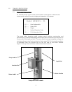
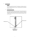
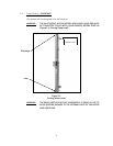
3.2 Right Angle Inlet and Vertical Position........................................................5
3.3 Discharge Screen Installation .........................................................................8
3.4 Priming Water Level.............................................................................................9
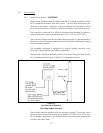
3.5 Two Sources of Power to the Single-Phase Controller.....................10
3.6 Changing Motor Rotation ...............................................................................11
3.7 “Rolling” the Leads to Balance Current Draw.......................................12
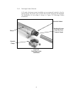
6.8 Liquid End and Motor Module ......................................................................20
6.9 Removing Liquid End ........................................................................................21
6.10 Liquid End Removed..........................................................................................21
6.11 Component Detail ..............................................................................................22
6.12 Rejoining Liquid End to Motor Module......................................................22
8.13 QS1800V and QS2800V Series .....................................................................24
9.14 Parts Schematic ..................................................................................................25
LIST OF T
ABLES
T
able Description
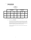
2.1 Pump Performance Summary................................................................3