


11
Installation Instructions.
Mounting System Installation
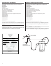
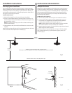
Pick a location under the sink to mount the system. Location should be
easily accessible, with clearance between the bottom of the filter canisters
and the floor or bottom of the cabinet; any less will result in difficulty of
removing filter canisters (see Fig. 5). Allow enough space on either side of
the system for the tubing connections.
SCREW INSTALLATION
1. Remove this template from the manual for easier installation.
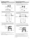
2. The top of the template openings should be placed a minimum of 17
inches above the bottom of the cabinet or floor where the system is to
be mounted (Fig. 4 and 5).
NOTE: Any distance lower may result in filter canisters interfering with
the floor when removed.
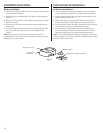
3. Tape template to wall, then mark the wall where the screws are to be
installed.
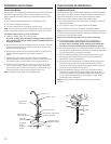
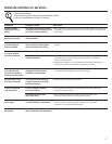
Install screws into the wall, leaving 3/16 inch clearance between the head
of the screw and wall (drill pilot holes if needed) (Fig. 6).
Instrucciones de instalación.
Montaje del sistema
Seleccione una ubicación debajo del lavaplatos para instalar el sistema.
La ubicación debe ser de fácil acceso, con espacio entre la base de los
cartuchos de los filtros y el piso o la base del gabinete; cualquier espacio
inferior presentará dificultades para retirar los cartuchos de los filtros
(Fig. 5). Permita suficiente espacio para cualquier lado del sistema para
las conexiones de la tubería.
INSTALACIÓN DEL TORNILLO
1. Remueva esta plantilla del manual para una instalación más fácil.
2. La parte superior de las aberturas de la plantilla deben colocarse
a un mínimo de 17 pulgadas por encima del fondo del gabinete
o del piso donde el sistema será montado (Figs. 4 y 5).
NOTA: Cualquier distancia menor podría resultar en que los cartuchos
de los filtros interfieran con el piso cuando sean removidos.
3. Pegue la plantilla a la pared con cinta adhesiva, luego marque la pared
donde los tornillos serán instalados.
Instale los tornillos en la pared, dejando un huelgo de 3/16 de pulgada
entre la cabeza del tornillo y la pared (taladre agujeros pilotos si es
necesario) (Fig. 6).
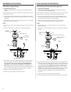
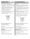
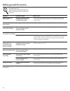
17 inches /
17 pulgadas
5 inches /
5 pulgadas
Bottom of Cabinet or Floor / Fondo del gabinete o piso
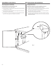
Template for screw hole pattern on back of filtration system /
Plantilla para el marco de los agujeros de los tornillos en la parte posterior del sistema de filtración
Fig. 4
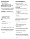
17 inches /
17 pulgadas
5 inches /
5 pulgadas
Screws /
Tornillos
Screw /
Tornillo
3/16 inch /
3/16 de pulgada
Fig. 6
Fig. 5
Wall / Pared