


10
Step-by-step installation instructions.
Customer Service Troubleshooting Tips Operating Instructions Safety InstructionsInstallation InstructionsCustomer Service Troubleshooting Tips Installation Instructions Safety InstructionsOperating InstructionsCustomer Service Troubleshooting Tips Installation Instructions Safety InstructionsOperating Instructions
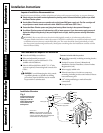
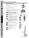
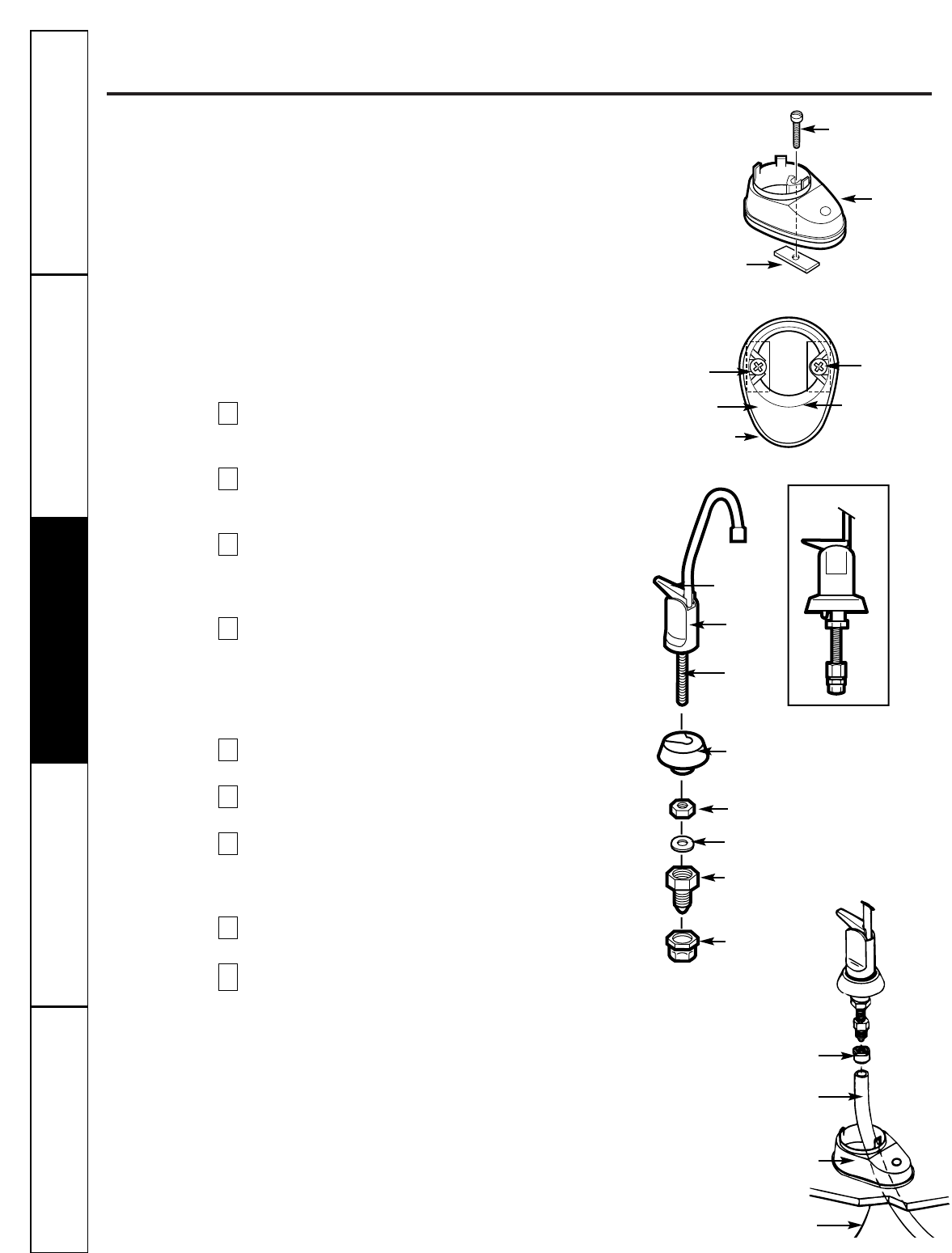
Electronic Faucet Installation
Be sure there is room underneath the sink to make the
needed connections. Select one of the following places to
install the faucet:
—IN an existing sink spray attachment or soap dispenser
hole.
—IN a hole to be drilled in the sink top.
—IN a hole to be drilled in the countertop, next to
the sink.
NOTE:
Looking at Fig. 3D, be sure the faucet base will fit
flat against the surface at the selected location so the
gasket will seal. The base may have to be angled sideways
or diagonally.
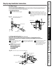
If drilling is needed, make a 1″-1 1⁄4 ″dia. hole.
Be
sure to use the proper procedure for drilling porcelain
or stainless steel. Special drill bits may be needed.
Looking at Fig. 3A, insert a screw into the NON-
SLOTTED base mounting hole. Turn a flat nut
a few turns onto the screw.
Position the base gasket over the mounting hole. Set
the base on the gasket, routing the leadwire through
the mounting hole. Holding the flat nut under the
sink with one finger, tighten the screw until just snug.
Turn the remaining flat nut a few turns onto
the other screw. Position the screw in the slotted base
mounting hole and tighten until snug. Make sure the
gasket position is properly aligned and
carefully tighten
both screws until the base is held firmly in place.
Do
not overtighten
and break the base.
Assemble the top faucet base and hex nut onto the
faucet stud (Fig. 3C). Tighten the nut until snug.
Insert washer into tubing adapter. Securely tighten to
faucet stud.
Feed the length of 3⁄8″ OD tubing from the bottom,
up through the faucet base. Connect to the tubing
adapter as shown in Fig. 3D., tightening the
compression nut securely.
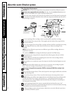
Remove the short shipping tube and insert the spout
into the faucet body.
Lower the faucet assembly and lock into place
on the faucet base.
9
8
7
6
5
4
3
2
1
Fig. 3A.
Faucet
base
Nut (2)
Screw (2)
Fig. 3B.
1″-1 1/4″ dia.
mounting
hole in sink or
countertop
Gasket
Faucet
base
TOP VIEW
Screw (2)
Nut (2)
Fig. 3D.
Base leadwire connector
(to battery pack)
3/8″ tubing, (run
to Filter 2 outlet)
Faucet base
Compression nut
Fig. 3C.
Washer
Hex nut
Top faucet base
Faucet
Lever
Spout
Faucet stud
Compression
nut
Tubing
adapter
ASSEMBLED