


5
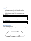
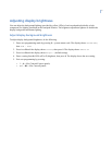
Figure 3. Touchpad wiring connections
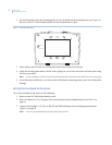
Attaching the touchpad to the mounting plate
Align the tabs at the top of the mounting plate with the slots on the touchpad and swing the touchpad bottom
toward the mounting plate. Gently tighten the screw into the bottom of the touchpad.
Power-up and bus communication
After making all wiring connections from the touchpad to the panel, you are ready to power up the panel and
verify correct communication between the touchpad and the panel. Upon power-up, the panel scans the bus for
connected devices and automatically learns the unit number of each bus device.
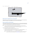
Note: If you plan to install systems with no alphanumeric touchpads, we recommend that you keep an alphanumeric
touchpad with you, specifically for installer programming. This touchpad can be quickly connected and disconnected
from the header pins on the lower-left portion of the panel, just above the terminal strip.
To power up the panel and verify bus communication:
1. Verify that all wiring between the panel and touchpad is correct.
2. Connect the panel battery and plug in the panel transformer. The touchpad should display
BUS SCAN,
then show a time display with the
PRESS STATUS prompt in the upper-left corner.
Note: If the touchpad does not power up (show any display) or respond as described above, unplug the panel AC
transformer and disconnect the backup battery. See Troubleshooting on page 9 for more information.
GND
Bus B
Bus A
+12V