


FTP-1000
Installation Manual
4
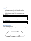
2. For wall mounting, place the mounting plate on the wall and mark the mounting holes (see Figure 2).
Be sure to leave a 3-inch clearance below for the touchpad door to open.
Figure 2. Mounting hole locations
3. Insert anchors into the wall at the marked locations where studs are not present.
4. Align the mounting plate holes with the wall or gang box screw holes and secure the back plate using
the screws provided.
Note: Do not overtighten screws or the mounting plate may bind and prevent the touchpad from mounting properly.
5. For wall-mount installations, cut a hole in the wall behind the mounting plate to pull the wiring cable
through.
Wiring the touchpad to the panel
To wire the touchpad to the panel, do the following:
1. Remove panel AC and backup battery power.
2. Run a 4-conductor, 18- to 22-gauge wire from the panel to the touchpad location (see Table 2 on
page 3).
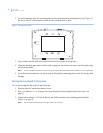
3. Connect the touchpad +12V, Bus A, Bus B, and GND terminals to the matching panel terminals
(Figure 3 on page 5).
Note: The wiring should extend from the right side of the connector.