


9
Thermal Expansion
Determine if a check valve exists in the inlet water line. Check with your local water
utility. It may have been installed in the cold water line as a separate back flow preventer, or it
may be part of a pressure reducing valve, water meter or water softener. A check valve located in
the cold water inlet line can cause what is referred to as a “closed water system”. A cold
water inlet line with no check valve or back flow prevention device is referred to as an “open”
water system.
As water is heated, it expands in volume and creates an increase in the pressure within the water
system. This action is referred to as “thermal expansion”. In an “open” water system,
expanding water which exceeds the capacity of the water heater flows back into the city main
where the pressure is easily dissipated.
A “closed water system”, however, prevents the expanding water from flowing back into the
main supply line, and the result of “thermal expansion” can create a rapid and dangerous
pressure increase in the water heater and system piping. This rapid pressure increase can quickly
reach the safety setting of the relief valve, causing it to operate during each heating cycle.
Thermal expansion, and the resulting rapid, and repeated expansion and contraction of
components in the water heater and piping system can cause premature failure of the relief
valve, and possibly the heater itself. Replacing the relief valve will not correct the problem!
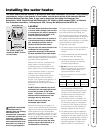
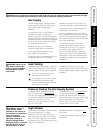
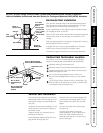
The suggested method of controlling thermal expansion is to install an expansion tank in the cold
water line between the water heater and the check valve (see illustration below). The expansion
tank is designed with an air cushion built in that compresses as the system pressure increases,
thereby relieving the over pressure condition and eliminating the repeated operation of the relief
valve. Other methods of controlling thermal expansion are also available. Contact your installing
contractor, water supplier or plumbing inspector for additional information regarding this subject.
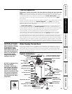
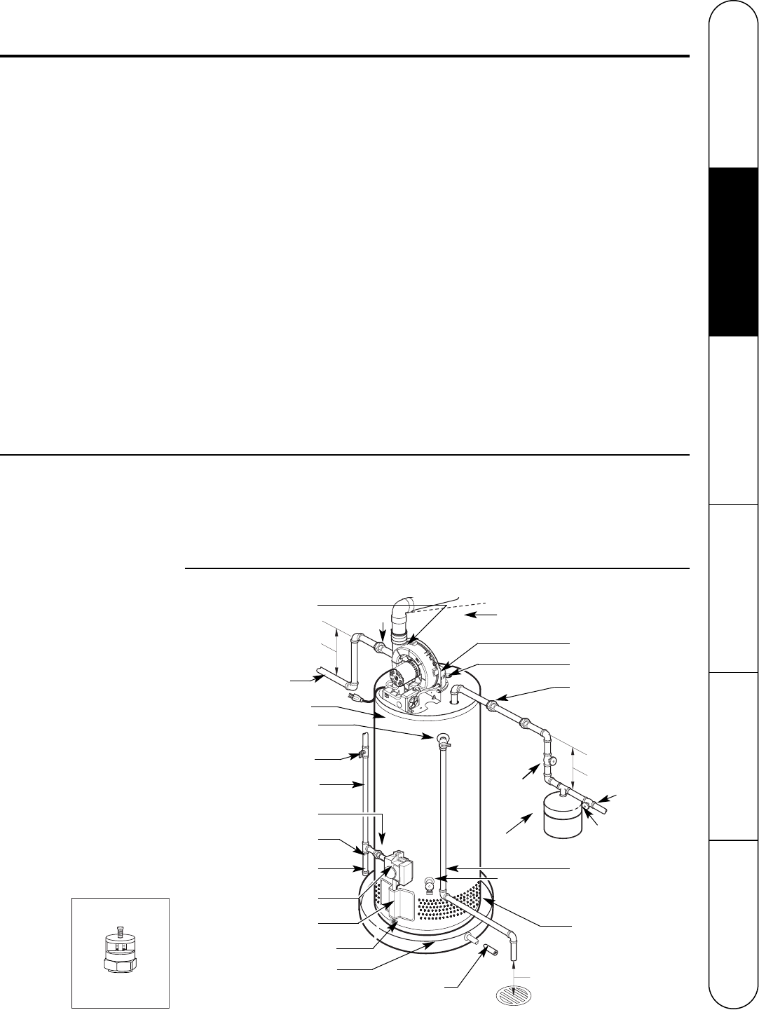
Typical Installation
C
O
L
D
H
O
T
Heat trap
6” minimum
Heat trap
6” minimum
Union
Hot water outlet
to fixtures
Temperature and
pressure relief valve
Relief valve
discharge line to
suitable open drain.
To gas supply
Sediment trap
Cap
Jacket door
Auxiliary catch pan
Ground joint union
Drain
valve
Drain Pan Pipe
to suitable drain.
To cold water
supply
6” Air gap
Blower assembly
1/4” per foot maximum slope up
or down for horizontal venting
Union
Thermostatic gas valve
Anode
Vent connector
to chimney
Manual gas shut-off
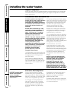
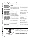
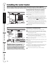
Water Supply Connections
Refer to the illustration below for suggested typical installation. The installation of unions or
flexible copper connectors is recommended on the hot and cold water connections so that the
water heater may be easily disconnected for servicing if necessary. The HOT and COLD water
connections are clearly marked and are 3/4” NPT on all models. Install a shut-off valve in the cold
water line near the water heater.
IMPORTANT: Do not apply
heat to the HOT or COLD
water connections. If sweat
connections are used,
sweat tubing to adapter
before fitting adapter to the
cold water connections on
heater. Any heat applied to
the cold water supply
fittings will permanently
damage the dip tube.
Shut-off valve
Shut-off
valve
Thermal expansion
tank (if required)
Combustion Air
Inlet Openings
Water Heater Jacket
NOTICE: The National Fuel
Gas Code (NFGC)
mandates a manual gas
shut-off valve: See (NFGC)
for complete instructions.
Local codes or plumbing
authority requirements may
vary from the instructions
or diagrams provided and
take precedent over these
instructions.
Vacuum Relief Valve
(Not Supplied)
If required, install per local codes
and valve manufacturer’s
instructions.
Flammable Vapor Sensor
Safety Instructions Installation Instructions Operating Instructions Care and Cleaning Troubleshooting Tips Customer Service