


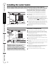
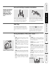
For increased energy efficiency, some
water heaters have been supplied with
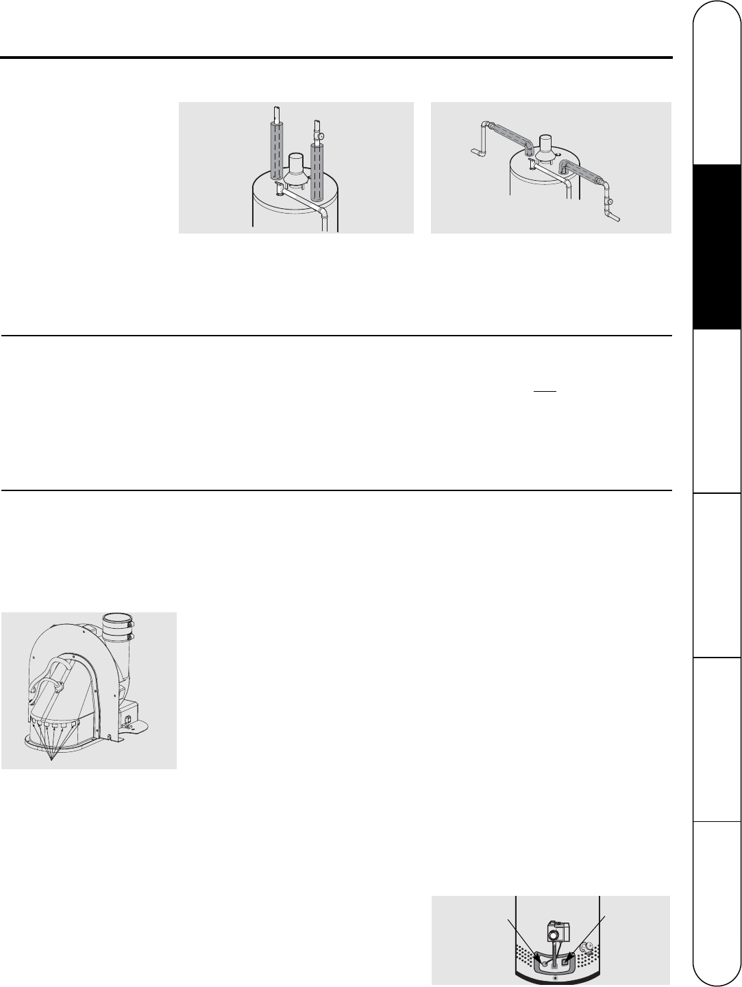
two 24” sections of pipe insulation.
Please install the insulation, according to
the illustrations above, that best meets
your requirements.
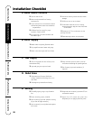
DO
❑ DO check inlet gas pressure to ensure
that it is within the range specified on the
rating plate.
❑ DO provide adequate air for combustion
and ventilation as discussed in the Use and
Care Manual and the National Fuel Gas Code.
❑ DO maintain proper clearances to
combustibles as specified on the rating
plate.
❑ DO allow enough time for joint cement
vapors to dissipate BEFORE applying power
to the water heater.
❑ DO ensure that the venting system
complies with the guidelines found in the Use
and Care Manual and National Fuel Gas
Code.
❑ DO contact a qualified service technician
if the pilot or main burner will not stay lit. The
burner chamber is designed to be sealed
utilizing a gasket and tamper resistant
screws.
DON’T
❑ DON’T block or restrict Combustion Air
Inlet Openings or the Flammable Vapor
Sensor located around the lower portion of
the water heater jacket.
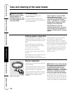
❑ DON’T block or restrict the Blower
Assembly Dilution Air holes.
❑ DON’T remove the Burner Access Door
unless absolutely necessary. This should
only be done by a qualified service technician.
A new burner access door gasket must be
installed on any burner access door that has
been removed.
❑ DON’T install this water heater where
standing water may occur. The base of the
water heater is meant to be mounted on a
dry surface.
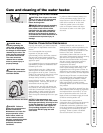
❑ DON’T operate the water heater if the
sight glass or burner access door grommet
is damaged or broken.
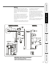
R
E
L
I
E
F
V
A
L
V
E
C
O
LD
H
O
T
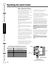
Typical vertical piping arrangement
R
E
L
I
E
F
V
A
L
V
E
COLD
HOT
Typical horizontal piping arrangement
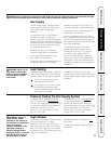
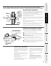
During Installation of this water heater...........
Heat Trap
Hot and Cold Pipe Insulation Installation
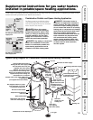
Burner Access
Door Grommet
Sight Glass
For increased energy efficiency, some
water heaters have been supplied with
factory installed 3/4” NPT heat traps in
the hot outlet line and cold water inlet
line.
These heat traps may
require a minimum
of one (1) 90
° 3/4” NPT elbow and may
require an additional 90° 3/4” NPT elbow
or a 3/4” coupling depending on your
installation needs. See Illustration of
nipples and heat traps on page 31.
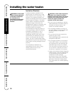
NOTICE: If pipe insulation
is used, ensure that the
thickness does not
exceed ½”. Insulation
thicker than ½” can
interfere with the Blower
Assembly Dilution Air
Holes.
19
Safety Instructions Installation Instructions Operating Instructions Care and Cleaning Troubleshooting Tips Customer Service
Blower Assembly Dilution Air Holes
Location of Dilution Air Holes