


15
NOTICE: All pipe, fittings, solvent cement, primers and procedures must conform to American
National Standards Institute and American Society for Testing and Materials (ANSI/ASTM) standards.
Vertical Vent Installation
Once the vent terminal location has been
determined, make a hole through the roof
and interior ceiling to accommodate the
vent pipe.
Complete the vent pipe installation to the
water heater's vent connector fitting on
the blower outlet.
Support vertical or horizontal runs as
previously mentioned.
Install adequate flashing where the vent
pipe passes through the roof.
Determine the vent terminal height and
cut vent pipe accordingly. Refer to the
above section for proper vent terminal
height.
Connect vent elbow onto vertical pipe
through roof.
Connect short piece of vent pipe
(approximately 3" long) to elbow, then
insert 1/2" mesh metal screen into
terminal elbow and join it to the short
piece of vent pipe.
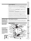
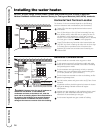
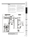
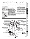
Vertical Vent Termination Location
The location of the vent terminal depends on the following
minimum clearances and considerations (see illustration):
Minimum twelve (12) inches above roof.
Minimum twelve (12) inches above anticipated snow level.
Maximum twenty-four (24) inches above roof level without
additional support for vent.
Four (4) feet from any gable, dormer or other roof
structure with building interior access (i.e., vent, window,
etc.).
Ten (10) feet from any forced air inlet to the building. Any
fresh or make-up air inlet such as a dryer or furnace area
is considered to be a forced air inlet.
Short Piece of Vent
Pipe
Min. 12" Above Roof
Min. 12" Above
Anticipated Snow
Level.
Max. 24" Above Roof
(Without Additional
Support)
Insert 1/2" Mesh Protective
Screen Inside Terminal Elbow
Vent Pipe
Through
Roof
Elbows
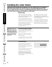
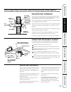
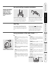
Horizontal Vent Installation
Once the vent terminal location has been determined, make a
hole through the exterior wall to accommodate the vent pipe.
Vent pipe must exit exterior wall horizontally only.
Insert a small length of vent pipe through the wall and connect
the coupling as shown to the left.
Place the 1/2" mesh metal screen inside the terminal fitting and
connect it as shown to the vent pipe on the exterior of the
building.
Seal any opening around the vent pipe or fittings with mortar or
silicone caulk as shown to the left.
Complete the rest of the vent pipe installation to the water
heater's vent connector fitting on the blower outlet.
If necessary support horizontal run as previously mentioned.
2' x 2' Sheet
Metal Shieldon
Brick or
Masonry Walls
Outside of
Building Wall
Mortar or
Silicone Caulk
From
Water Heater
Vent Pipe
Pipe Coupling
Vent Terminal
with
1
¼2" Mesh
Protective
Screen Inside
Safety Instructions Installation Instructions Operating Instructions Care and Cleaning Troubleshooting Tips Customer Service