


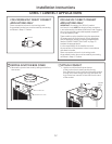
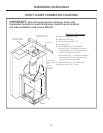
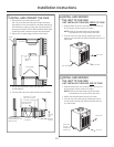
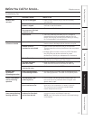
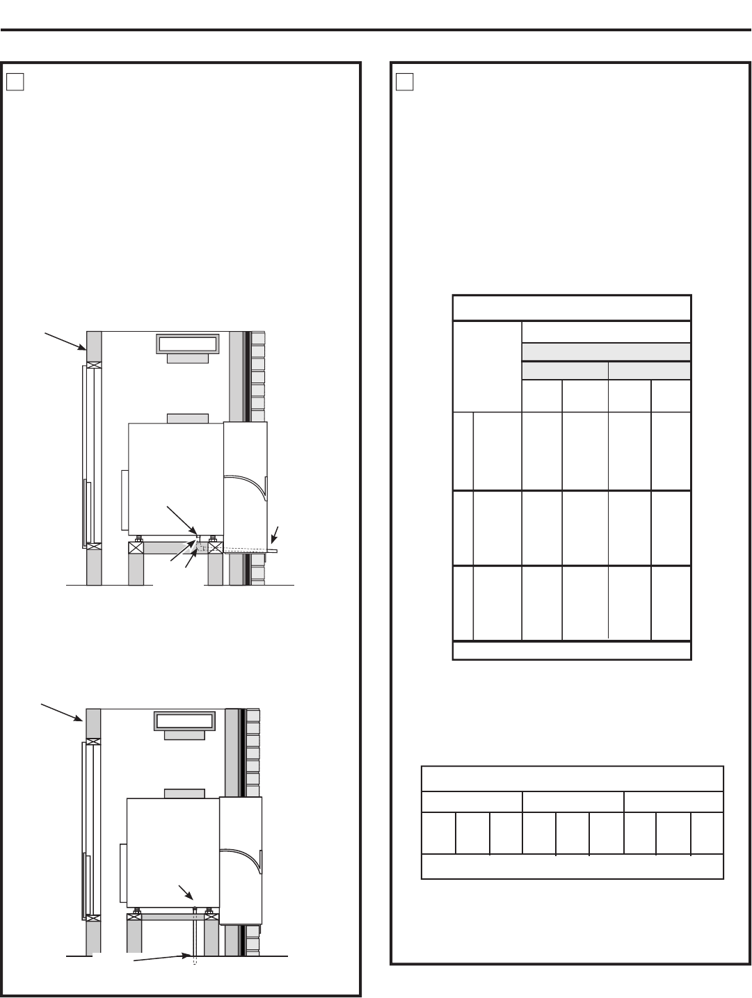
INSTALL THE DRAIN(S)
An external or an internal drain must be attached
to the primary drain connector. A secondary drain
is supplied if required by state and local codes. Refer
to the local codes for proper installation of the drains.
If the secondary drain is not used, seal its drain port
with a 3/4” MNPT plug.
External Drain
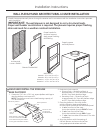
Attach a 90° PVC elbow to the unit’s female 3/4” NPT
drain connector. Use the other end of the elbow to run
a 3/4” Sch. 40 PVC pipe through the knockout holes of
both the wall plenum and the architectural louver to the
outside. Seal the gap between the plenum hole and PVC
tube. See the Installation Instructions in the RAVAL1.
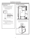
Internal Drain
Attach PVC to the unit’s female 3/4” NPT drain
connector. See the Installation Instructions
in the RAVAL1. Local codes may apply.
2
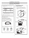
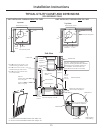
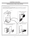
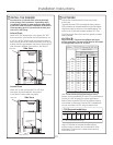
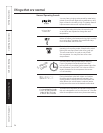
DUCTWORK
Prepare the closet ductwork for later connection
to the case.
The total flow rate (CFM) and external static pressure
(ESP) available can be estimated from the chart below.
Use these charts to select your fan speed setting. The
collar on top of the case accepts standard 10
”
duct.
Pull all duct tight. Extra duct slack can greatly increase
static pressure.
NOTICE: Flex duct can collapse and cause
airflow restrictions. Do not use flex duct for 90° bends
or unsupported runs of 5 ft. or more.
3
Installation Instructions
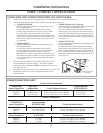
Your airflow should be balanced based on many
factors, such as available ESP, room CFM, and ductwork.
Consult an HVAC engineer for proper applications.
External static pressure (ESP) can be measured with a
manometer or pitot tube. Once this ESP is established,
you can calculate the CFM using the above chart.
CFM Recommendations
9,000 BTU 12,000 BTU 18,000 BTU
390 415 440 440 465 490 435 485 535
• • •
• = Recommended Mid Range
Higher CFMs tend to increase Sensible capacity,
enhance room circulation and increase duct noise,
while lower CFMs tend to increase Latent capacity
and reduce noise.
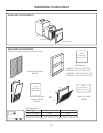
Side View
Inside wall
Female drain
fitting
3
⁄4”
PVC
90° Elbow
PVC
(External drain)
PVC
(Internal drain)
Side View
Inside wall
Female drain
fitting
3
⁄4”
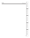
Airflow – CFM @ 230 Volts and @ 265 Volts
Indoor Fan CFM
DUCT SELECT SWITCH
UP DOWN
ESP
(in. water)
High
CFM
Medium
CFM
Medium
CFM
Low
CFM
0.0
0.1
0.2
0.3
0.4
520
500
480
440
400
460
415
370
265
160
460
415
370
265
160
360
290
220
-
-
0.0
0.1
0.2
0.3
0.4
590
570
550
480
410
500
465
430
345
260
500
465
430
345
260
380
325
270
-
-
0.0
0.1
0.2
0.3
0.4
600
585
570
510
450
520
485
450
375
300
520
485
450
375
300
400
340
280
-
-
AZ85(H/E)09AZ85(H/E)12AZ85(H/E)18
To correct for 208 volts: 0.91
19