


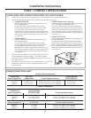
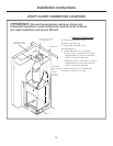
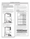
BUILD AND INSTALL THE ZONELINE
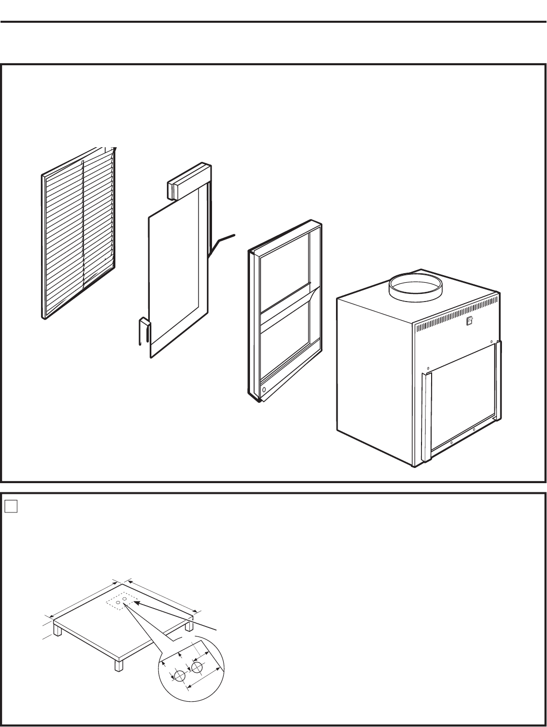
BASE PLATFORM
1. Construct a 23
1
⁄4” min. x 23
1
⁄4” min. square platform with legs to
raise the platform a minimum of 8”.
NOTE: The platform must have a load-bearing capacity of
175 lbs. minimum.
1
Installation Instructions
18
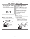
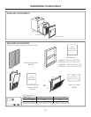
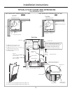
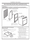
WALL PLENUM AND ARCHITECTURAL LOUVER INSTALLATION
• Install the appropriate wall plenum through the exterior wall in accordance with the Installation Instructions provided
with the plenum.
IMPORTANT: The wall plenum is not designed to carry structural loads.
Proper wall header construction is required. The plenum requires proper flashing,
shim and caulk for a weather resistant installation.
Properly square
and level plenum.
Proper header for
structural support.
Apply proper caulking
and flashing.
Architectural
Louver—RAVAL1
Exterior/Outside Wall
Case
Wall Plenum
RAVWP6 – 6”D x 19
3
⁄4”W x 32”H
RAVWP8 – 8
”D x 19
3
⁄4”W x 32”H
RAVWP12 – 12
”D x 19
3
⁄4”W x 32”H
RAVWP15 – 15
”D x 19
3
⁄4”W x 32”H
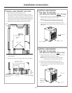
2. Make drain hole cutout(s):
• Primary Drain – Centerline of drain is
approximately 5
1
⁄4” from left platform edge
and 8
1
⁄2” from back platform edge.
• Secondary Drain – Centerline of drain
is approximately 6
1
⁄2” from left platform edge
and 5
1
⁄4” from back platform edge.
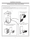
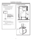
3. Place the platform in the utility closet
with the following clearance between it
and the interior surface of the walls/door/panel:
• 4” min. from front of the case –
Unit to be installed through FRONT of case
• 5” min. from front of the case –
Unit to be installed through SIDE of case
• 3” min. from two sides of the case (5” for side
installation).
4. Align the platform with the opening of
the wall plenum and secure to the floor
using appropriate brackets and bolts.
23
1
⁄4” min.
8”min.
for
drain
access
Cutout for drain
connection(s)
(see NOTE below)
Back of platform
Left side of platform
NOTE: Specific cutout size
for drain connections needs
to be determined by the installer
for the given installation situation.
5
1
⁄4”
23
1
⁄4” min.
5
1
⁄4”
6
1
⁄2”
8
1
⁄2”