


Installation Instructions
15
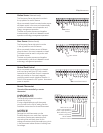
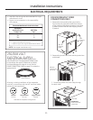
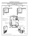
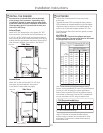
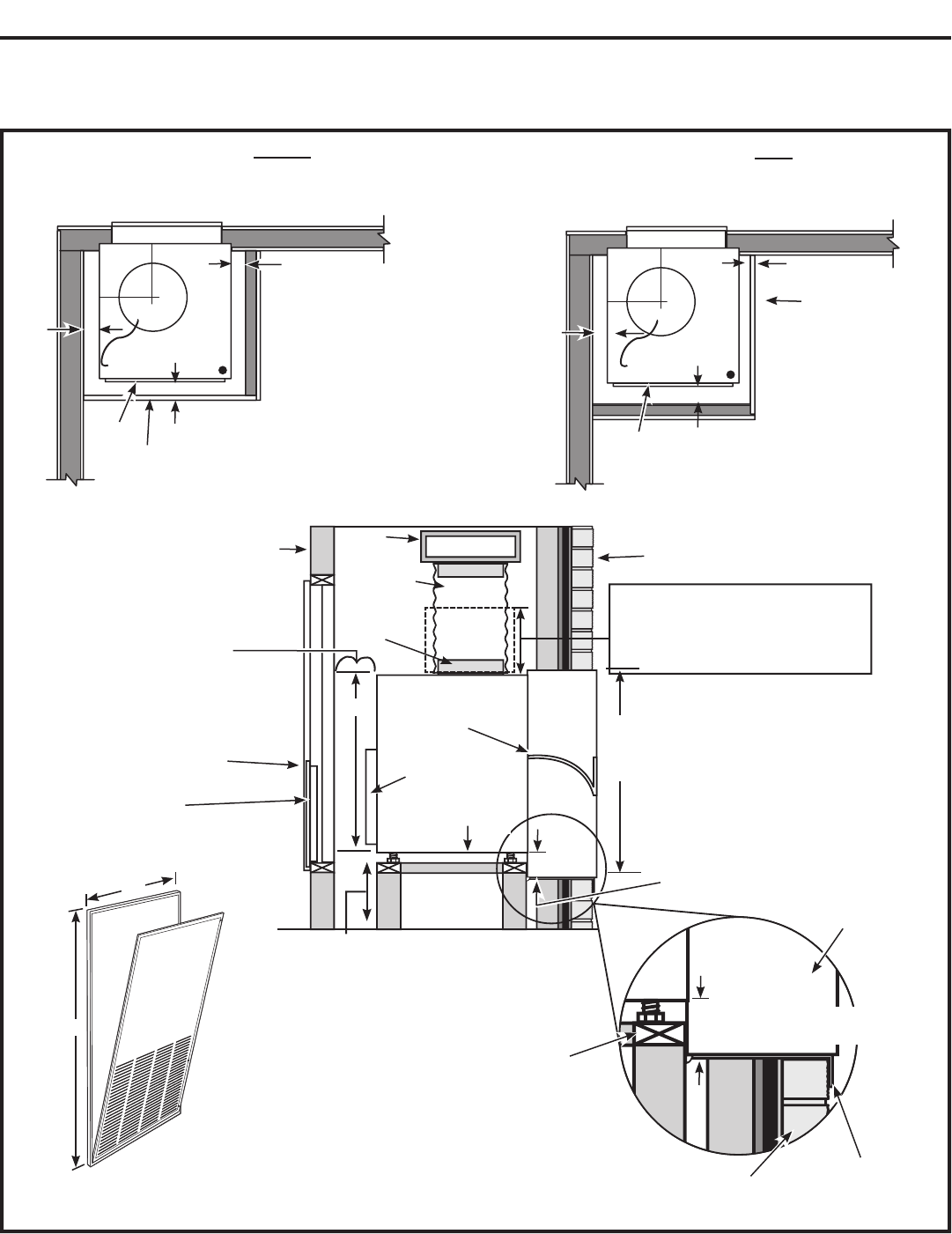
TYPICAL UTILITY CLOSET AND DIMENSIONS
(FOR REFERENCE ONLY)
Side View
Top View
Architectural Louver
10”
duct
Door/access panel
5” min.
5” min.
Unit front
3”
min.
14” min. – Required only if optional
Hydronic Heating Kit (RAVHW1, RAVHW2,
RAVHW3) is to be installed. Clearance
for installation should be taken into
consideration if this kit is to be used.
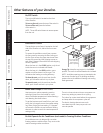
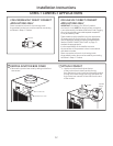
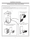
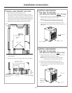
Exterior/Outside
Outside wall
Wall
plenum
Inside wall
Air discharge
outlet
Rigid
ductwork
Flexible or
rigid duct
Wall plenum
divider
31”
Option 1
Access panel with
return air grille
Option 2
Return air grille
Filter bracket
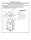
Secure platform
to the floor
Platform: 23
1
⁄4” x 23
1
⁄4” square
Min. load capacity: 175 lbs.
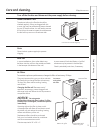
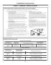
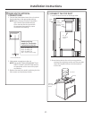
• 4" min. from front of case – Unit
installed through FRONT of case.
• 5" min. from front of case – Unit
installed through SIDE of case.
• 3" min. from two sides of case.
(5” for side install).
Plenum
cutout
32
1
⁄4” H
x 20” W
Drain fittings
3
⁄4”
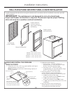
Outside wall
Platform
Wall plenum
Field supplied
outer flashing
10”
11
1
⁄2”
A
B
A Minimum recommended access door width: 30”
B Minimum recommended access door height: 50
”
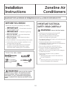
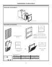
UNIT INSTALLED THROUGH SIDE OF CASE
Top View
Architectural Louver
10"
duct
Door/access panel
3" min.
4" min.
Unit
front
3"
min.
10”
11
1
⁄2”
UNIT INSTALLED THROUGH FRONT OF CASE
Bottom of case approx. 2”
above bottom of plenum
8”min.
for drain
access
Bottom of case approx. 2”
above bottom of plenum
Unit