


43
geappliances.com
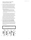
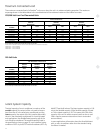
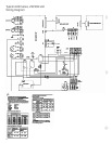
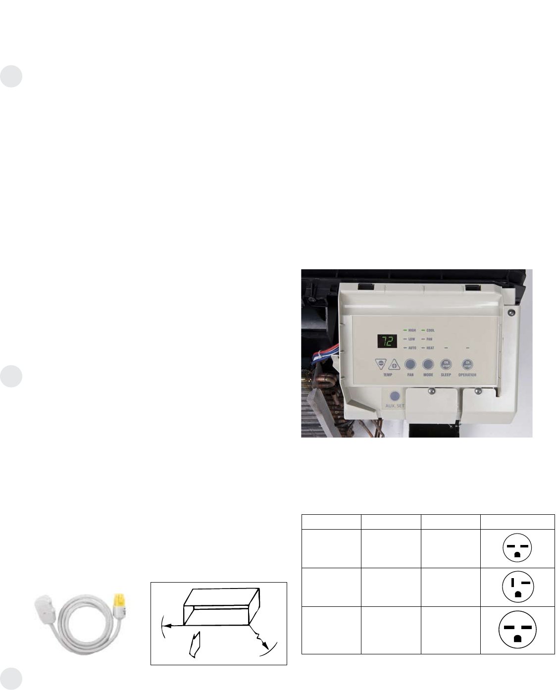
Type Mfg Part No Configuration
15 AMP
Tandem
NEMA6-15R
Hubbell
P&S
5661
5661
20 AMP
Perpendicular
NEMA6-20R
Hubbell
P&S
5461
5871
30 AMP
Large Tandem
NEMA6-30R
Hubbell
P&S
9330
5930
Essential Elements Ordering Overview
RAK4002A
Wiring harness can be ordered separately as RAK4002CW.
230/208-volt line-cord connected units — order line cord kit.
230/208-volt sub-base connected units — order sub-base
(includes power connection kit) and junction box for chassis
(if hard wired).
265-volt units — order sub-base and power connection
kit separately.
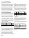
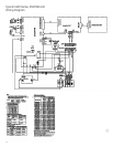
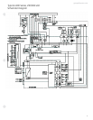
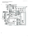
Electrical Wiring Information –
4100/6100 Series
All Zonelines are single-phase 60 hertz units.
For all installations, the feeder, sub-feeder, branch circuit
and electrical protective devices and selection must conform
to the National Electrical Code and to local codes.
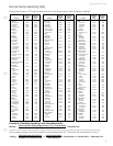
Maximum connected load in amperes, including demands
for the electric heater and the fan motor, are shown on
page 44. Branch circuit ampacity and electrical protective
device sizing are shown on page 42 for 230/208-volt and
for 265-volt units.
More than one unit per branch circuit is not recommended.
When in doubt, consult the National Electrical Code. All
wiring, including installation of receptacle, must conform
to local electrical regulations and codes.
Replacement of Existing Chassis
230/208-Volt and 265-Volt Units
There have been changes to NEC and improvements and
modifications to the Zoneline chassis and sub-bases since
the unit was first introduced. Some of these changes require
alterations to be made when replacing an older unit with a
new chassis.
Line-Cord Connected Units
The plug configuration of new line-cord connected units
complies with the current NEC standards. Older installations
may have wall receptacles that conformed to NEC standards
at the time the building was constructed and may not match
the configuration of the plug on the new line cord. The
recommended solution is to change the wall receptacle to
conform to current standard plug configuration. See chart
on this page for current receptacle configuration.
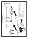
Permanently Connected Units With Sub-Base
If the existing unit is connected to a sub-base, the installation
of the new unit may involve modifying the existing installation
slightly. It is recommended these modifications be made by a
qualified electrician.
If the existing sub-base is the full width of the wall case,
RAK201 sub-base access plate may be ordered and used
to replace the cover on the old sub-base. Field-supplied
wiring, conduit and conduit connectors should be used to
make a connection between the new chassis and the center
knockout of the RAK201. The wiring connections should be
made inside the sub-base and the RAK201 attached to the
sub-base with the two screws provided.
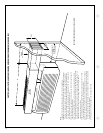
If the existing sub-base is not the full width of the wall case,
the electrician will have to modify the existing cover plate to
allow field-supplied wiring, conduit and conduit connectors to
be run from the permanent connection kit to the sub-base.
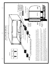
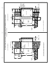
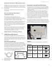
Typical Line-Cord
Power Connection Kit
RAK3203A shown
58"
21"
Inside
Maximum Cord Extension
Receptacle
Enclosure cover removed.