


23
geappliances.com
Sub-Base (Continued)
RAK204D30P 208/230 volt 30-amp receptacle. Receptacle
is NEMA6-30R with 18" of #12AWG wires attached to the
receptacle. Short power connection kit included.
Chaseway included.
The junction box (RAK4002A for 4100 and 6100 Series
units) that mounts on the chassis of 230/208 volt sub-base
connected units must be purchased separately.
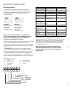
Sub-bases for the 265-volt units:
RAK204E15 265-volt 15-amp receptacle. Receptacle is
NEMA7-15R with 18" of #12AWG wires attached to the
receptacle. Chaseway included.
RAK204E20 265-volt 20-amp receptacle. Receptacle is
NEMA7-20R with 18" of #12AWG wires attached to the
receptacle. Chaseway included.
RAK204E30 265-volt 30-amp receptacle. Receptacle is
NEMA7-30R with 18" of #12AWG wires attached to the
receptacle. Chaseway included.
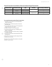
The junction box for 265-volt units is shipped with the
chassis since all 265-volt units are to be “permanently
(or direct) connected.”
The power connection kit is not included
There are separate internal compartments to permit
separation of low-voltage (Class 2) connections from line-
voltage connections as required by NEC. Conduit containing
building wiring enters the sub-base through knockouts
located in the rear or bottom of the sub-base and is not
accessible when the wall case is installed.
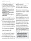
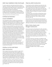
The sub-base attaches to the RAB71 wall case with two clips
(field-assembled) that are screwed into pre-drilled holes in the
bottom front flange of the wall case. It attaches to the RAB77
wall case with clips that fit over molded ribs without requiring
the use of screws into the wall case. See page 33 for illustration.
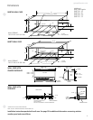
Since the sub-base extends under the wall case, clearance
from the inner edge of the wall case to the finished wall must
be 2-3/8" or greater. The sub-base has four leveling legs and
adjustable side channels to enable the area under the wall
case to be enclosed. Clearance from the bottom edge of the
wall case to the finished floor must be between 3" and 5".
The sub-base may be used as support for the chassis and
wall case in installations where the wall is of insufficient
thickness to provide secure mounting of the wall case.
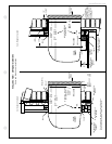
Wall Case Installation Data
General
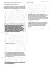
Generally, Zoneline units are installed 3" to 5" above the
floor (flush to finished floor installation is possible) as near
to the center of the room as possible; underneath a window
or a glass panel is typical. Normal installation of the wall
case allows installation flexibility; from flush with the
finished interior wall to a minimum of 1/4" of the wall case
extending beyond the finished exterior of the building. Special
consideration must be given to installations where the wall
case does not extend a minimum of 1/4" beyond the finished
exterior wall. See pages 30 and 31 for information on this type
of installation. The unit may be installed high in the wall and
these installations usually require a remote thermostat and
are discussed on pages 15 and 16.
Regardless of the installation, there are several things to
consider when selecting a location for installing the unit.
For instance, drapery location could interfere with air
discharge, and placement of furniture may have an impact
on the performance of the unit. The following information
is intended to minimize installation problems and assure
you of trouble-free installation.
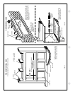
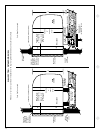
Refer to page 21 for required wall opening dimensions.
Minimum recommended interior and exterior case projections
for standard wall thicknesses are shown in the drawings in
this manual. The case may be installed flush with the finished
indoor wall. Special attention must be paid to room-side case
projection when the unit is installed in a ducted application
as shown on pages 38 and 39.
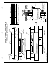
In walls thicker than 13-1/2" for line-cord-connected units
and 11-1/8" for sub-base installations, it may be necessary
to install a field-fabricated case extension or use one of the
special- order RAB71 deep wall cases. Such extensions must
be carefully flashed and sealed both to the wall case and to
the wall to ensure water integrity. This is necessary to ensure
that any water entering the wall case, either from operation
of the unit or from other sources, such as rain storms or from
washing the exterior of the building, will drain from the case
without the possibility of capillary action drawing the water
into either the room or the wall cavity. In an installation where
the case is recessed less than 3" from the outside surface,
flashing and sealing may be all the modification necessary.
In such an installation, the sides and top of the wall opening
must be waterproof to prevent moisture from seeping into
and damaging the walls. See pages 30 and 31 for suggested
detail. Since the installation of a case extension requires a
considerable amount of attention, we recommend using
one of the deep wall cases if the standard case is not of
sufficient depth.
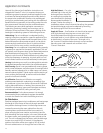
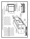
Mounting an outdoor grille or louver section to the building
face may cause a space between the outdoor coil and the
louver section. Air splitters, aligned with the ends of the
outdoor coil, must be installed between the outdoor coil inlet
and outlet air streams. Gaps between the outdoor coil and
the louver section may allow condenser air recirculation and
affect the operation of the unit. See page 41 for requirements
for custom louvers.
The wall case should be level from side to side and
from level to 1/4 bubble tilt to the outdoors. The
condensate disposal system in the unit is designed
to dissipate the condensate water generated
during cooling operation in accordance with ARI
standards and actually uses this water for maximum
unit efficiency. A level unit will also ensure proper
performance of the Internal Condensate Removal (ICR)
system optional on heat pump units.