


13
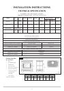
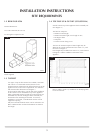
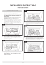
3.1.5 To set the flue length, measure the total wall thickness, then
add 65mm. This total flue length will give the minimum
clearance of 50mm between the rear of the stove and the
wall. To cut the flue to length using a hacksaw, first insert
the square cardboard fitment into the flue. This will support
the inner flue. Cut through the flue and fitment. See diagram
2. ENSURE THE REMAINING FITMENT IS REMOVED
FROM THE FLUE. File the cut edges of the flue smooth.
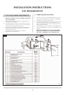
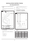
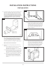
3.1.6 From outside, locate the flue assembly into the hole until the
terminal is flat against the wall. Ensure the terminal is
vertical. NOTE THE ORIENTATION OF THE TERMINAL.
See diagram 3. Mark the four fixing holes, remove the
terminal and drill the holes, inserting the rawplugs supplied.
DO NOT FIX THE FLUE AT THIS STAGE.
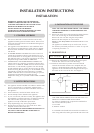
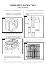
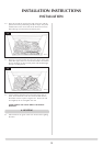
3.1.7 Position the stove ensuring all appropriate clearances are
observed.
3.1.7a When installing with a top flue, please note the flue
pipe fits through a hole in the top grill, the
dimensions are for floor fixing a top flue installation
with clearance for side panels.
3.1.7b Position the engine assembly in its intended location
and mark the position of the floor fixing holes at the
base of each side of the subframe, minimum fixing
dimensions to a rear wall are showin in Diagram 3.
3.1.7c Remove the assembly and drill the two holes using a
No.12 masonry bit. Push the rawl plugs into the
holes and place the engine assembly in position.
Secure to the floor using the screws provided. Sea
Diagram 3.
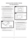
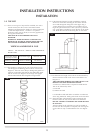
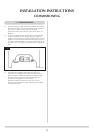
3.1.7d Having run the gas supply to the stove, PURGE THE
SUPPLY. This is essential to expel any debris that
may block the gas controls. Connect the gas supply
to the 8mm compression elbow at the RH rear
corner of the stove, ensuring that the pipe position
does not interfere with the location of the outer
casing. See Diagram 4.
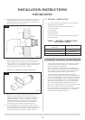
3.1.7e Open the second carton and carefully remove the
ceramic outer casing components. Gently position
the LH side so that the bolt heads on the engine
subframe locate in the keyhole slots on the back of
the panel and gently slide into place so that the
ceramic comes to rest on the floor. Repeat the
procedure for the RH side. See Diagram 5.
INSTALLATION INSTRUCTIONS
INSTALLATION
2
AR0630
3
AR0631
4
AR0934
5
AR0488