Stovax 8700CFCHEC Stove User Manual


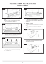
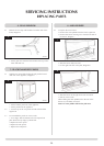
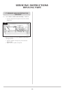
7. MAIN CONTROL ASSEMBLY
7.1 To access the main control assembly, first remove:
 
 
 
 
 
7.2 To remove the splitter plater:
 
 
 
9
AR1966
All components can be replaced without removing the
control assembly.
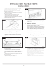
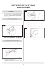
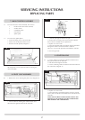
8. PILOT UNIT ASSEMBLY
  
10
AR1963
 
disconnect the ignition lead from the electrode
27
11
AR0097
13mm
4.0mm
 
 
sleeve which is needed for the replacement
 
 
through the vida flex and secured with a cable tie
There is a cut out in the pilot shroud to hold the vida flex.
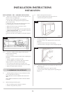
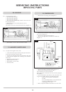
 
9. IGNITION LEAD
  
the ignition lead from the electrode
 
 
the control box, Diagram 12
12
AR1963
 
 
with a cable tie and the red insulated end is attached to the
electrode
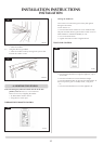
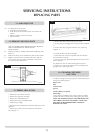
NOTE: DO NOT ROUTE THE IGNITION LEAD IN THE
VICINITY OF THE ANTENNA ON THE CONTROL BOX.
THIS DAMAGES THE COMPONENTS.
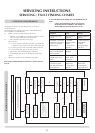
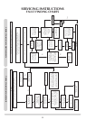
SERVICING INSTRUCTIONS
REPLACING PARTS