


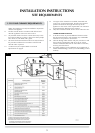
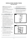
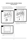
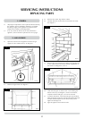
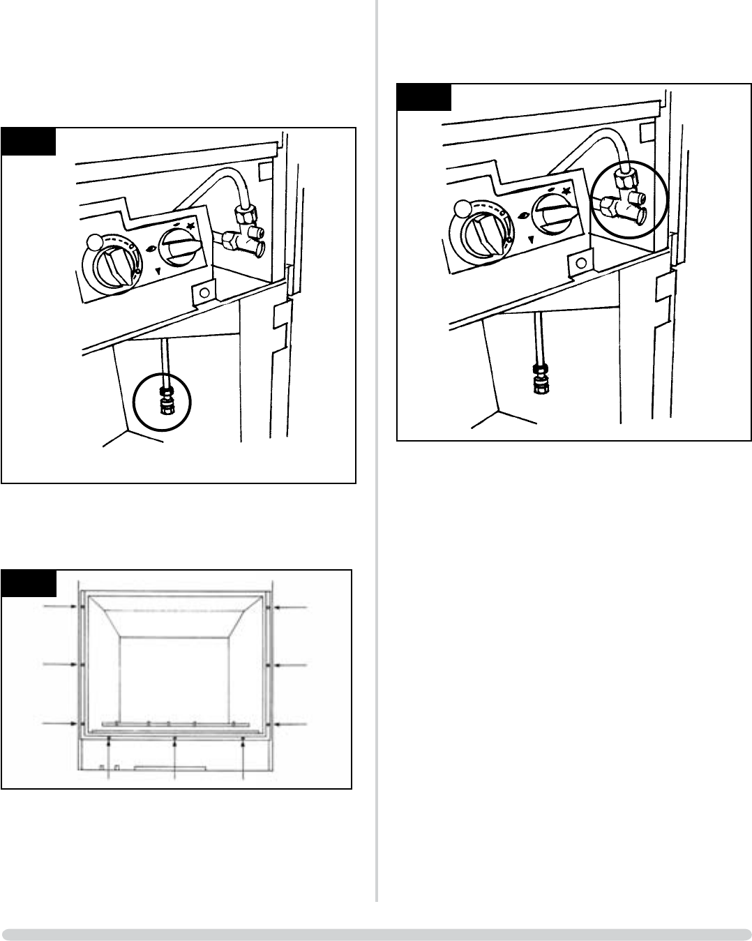
3.16 It is now necessary to connect the gas supply to the
appliance. The gas supply may enter through the floor
directly under the appliance or through the knockout panel
in the rear RH corner of the outer casing. In both instances,
a preformed pipe is ready fitted and connection should be
made to the compression fitting on the end of this pipe. See
diagram 10.
10
AR1294
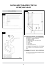
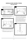
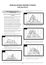
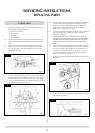
3.17 Ensure the front door is open by depressing centrally on the
RH side; remove the glass frame assembly by unscrewing
the nine retaining screws. See diagram 11.
11
AR0816
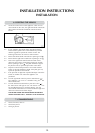
3.18 Carefully remove the box containing the logs and place to
one side. Remove the cardboard fitment that protects the
factory fitted ceramic panels; take care as these are easily
damaged.
15
INSTALLATION INSTRUCTIONS
INSTALLATION
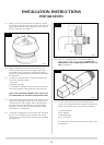
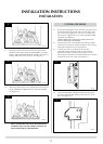
3.19 Connect a suitable pressure gauge to the test point located
on the inlet fitting and turn the gas supply on. Check all
connections for leaks paying particular attention to the
fittings at each end of the inlet pipe. See diagram 12.
12
AR1294
3.20 Light the appliance and check the rest of the joints for leaks.
Turn the appliance to maximum and check the supply
pressure is as stated on the databadge. Turn the gas off and
replace the test point screw, turn the gas back on and check
the test point for leaks.